REPAIR 800D
6-2
Published 5-27-2018 Control # 039-06
CYLINDER DISASSEMBLY AND REPAIR
1. Disconnect shaft end of cylinder from machine.
2. Retract cylinder shaft with oil from the hydraulic system
until about 12 in (30 cm) of shaft is extended. The barrel
must be filled with oil to prevent a compressed air
chamber being formed which could result in injury at
disassembly.
3. Remove the cylinder from the machine and place on
supports with an oil pan directly beneath the cylinder
head area.
4. Using the proper size of internal snap ring pliers,
compress the snap ring completely and remove from
groove.
5. Attach a porta power hand pump or hydraulic line from
crane circuit valve to the shaft end of the cylinder. Debur
snap ring groove edge. Failure to do so will damage
barrel or packing gland.
6. Operate hand pump or crane circuit valve, preferably the
boom telescope circuit, to force packing gland out of
barrel.
7. Remove the shaft and piston assembly by hand.
8. Disassemble the piston set by removing nut, replace
worn or damaged parts. Note: Loctite® 680 is used
during original assembly to secure nut to shaft. If
necessary, heat nut to 400-500°F (204-260°C) to
facilitate removal. If heat is necessary for removal,
discard nut and replace with new equivalent nut as well
as worn or damaged parts.
9. Wipe and inspect cylinder barrel for internal damage.
10. Wipe and inspect cylinder shaft for damage.
11. Remove shaft packing by removal of internal snap ring
from packing gland. If spiral rings are used, they will
have to be replaced each time they are removed.
Replace parts as required.
12. Lubricate piston head snap ring at O-ring seal area
removing all nicks that have been formed at the snap
ring area that would damage the O-ring before
installation.
13. Reassemble shaft and piston set assembly. Apply
Loctite® to nut and onto shaft using type 680 according
to Loctite® recommendations.
14. Reinstall shaft and head assembly being sure that snap
ring expands completely and properly into the snap ring
head groove.
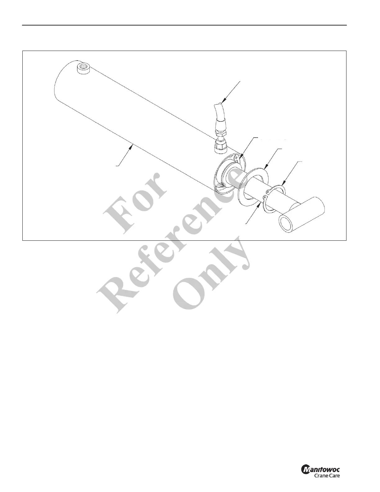
PRESSURE LINE FROM PORTA-
POWER OR HYDRAULIC LINE FROM
CRANE CIRCUIT VALVE
READ PARAGRAPH 5 & 6 BEFORE
PERFORMING THIS STEP
SNAP RING
WASHER
SNAP RING
SHAFT EXTENDED
CYLINDER BARREL
Fo
r
Reference
Only

 Loading...


