National Crane Published 5-27-2018 Control # 039-06 2-3
800D OPERATION
Capacity Chart – This chart shows capacities of crane at
various operating areas and hoist capacities with appropriate
reeving.
Boom Angle Indicator – Located on either side of the base
boom section and used to determine main boom angle with
respect to horizontal. For reference only.
Boom Length Indicator – Located on either side of the
second boom section. The letters on the intermediate boom
lengths correspond to the letters on the capacity chart. The
length indicators are used to define boom length and with the
capacity chart and load radius are used to determine the
maximum loads that may be safely lifted. Actual radius must
be measured from the centerline of rotation.
Load Radius – Horizontal distance from the center of
rotation of the turret to the center of the loadline hook or load
with the load suspended. Use boom angle and boom length
as a reference to determine loadline or load radius. When
lifting maximum rated load, always know the weight of the
load and measure the radius with the load suspended.
HYDRAULIC CAPACITY ALERT (HCA)
SYSTEM (IF EQUIPPED)
Note: HCA system cannot be used with jibs and/or
personnel platforms.
HCA Load Range Gauge – Aid in determining the load
condition of crane. The gauge has three colors on the dial
face: (1) Green – OK; (2) Yellow – Caution; and (3) Red –
Overload. Do not use the Load Range Gauge with a jib.
Refer to “Hydraulic Capacity Alert System” for more
information.
HCA Overload Light – Indicator light illuminates when HCA
detects crane overload and boom down, extend out and
hoist up functions disabled.
ATB Light – Indicator light illuminates when a two block
condition is detected.
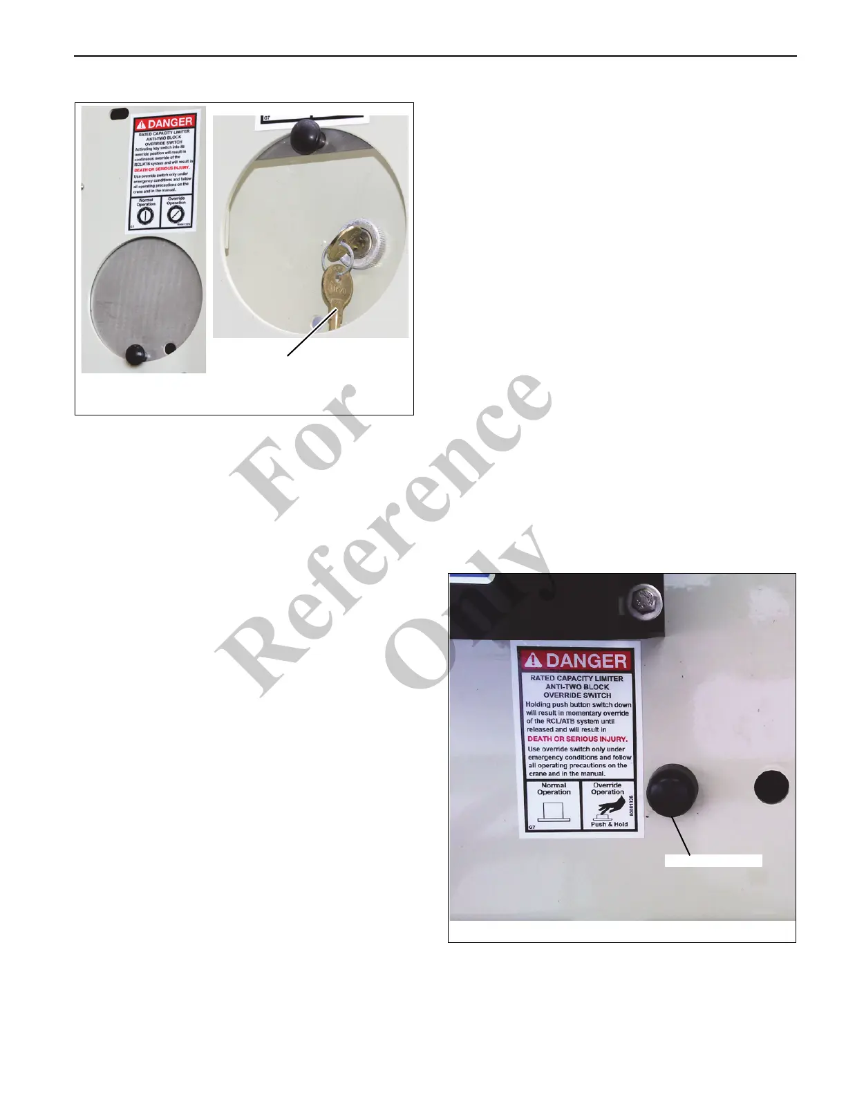
Override Key Switch – The Override Key Switch
(Figure 2-1) continuously overrides HCA/ATB lockout
conditions in emergency situations. When the key switch is
turned to the ON position, the system overrides HCA/ATB
lockout condition until the key is turned to the OFF position.
Some units may be equipped with a Manual Reset Valve
option that does not have Override Key Switch. Do not use
override to continue lifting operations in an overload or two
blocked condition.
Override Button – The override button (Figure 2-2)
temporarily overrides HCA/ATB lockout conditions in
emergency situations. On newer versions of the 800D, when
the button is pressed, the system momentarily overrides the
lockout condition until the button is released. The override
button is centrally located between operator stations,
between the frame and outrigger motion alarm. On older
versions of the 800D, with Override Key Switch in ON
position, depress button to override the OMS and HCA
systems. Do not use override to continue lifting operations in
an overload or two blocked condition.
Override Key Switch
FIGURE 2-1
9354
9355
FIGURE 2-2
Override Button
9356
Fo
r
Reference
Only

 Loading...


