OPERATION 800D
2-4
Published 5-27-2018 Control # 039-06
RATED CAPACITY LIMITER (RCL) (IF
EQUIPPED)
NOTE: Consult the RCL manual in the event of a RCL
malfunction.
The RCL system is a CANbus system that coordinates and
displays information about the crane conditions during
operation. Information about the following is reported to the
operator in real time on the operator console:
• Boom length and angle
• Outrigger status
• Crane hydraulic load
Reference data, such as load charts, boom weights, and
dimensions, are stored in memory in the QScale console and
used to calculate operating conditions. When operating limits
are reached, the RCL generates warning signals that appear
on the operator console. If operating limits are met, the RCL
will stop aggravating crane movements, like hoist up or
telescope out.
The RCL is powered by a 12V input from the truck battery
through a 15 Amp fuse. A toggle switch in the truck cab turns
the RCL system ON and a light next to the switch indicates
when the RCL is active. The RCL memory always has power
supplied by the truck battery even when the truck ignition is
in the OFF position.
The RCL features the following components:
cScale iFlex DIO – The cScale iFlex coordinates the inputs
from and outputs to the different components in the RCL
system. It is located inside the frame gusset under the turret.
QScale Operator Console – The QScale operator console
displays data about the crane the operator needs to operate
the crane effectively and safely, including the status of the
outriggers, boom status and load chart information. The
monitor is mounted on a swing arm on the front assembly
and can be adjusted for use on either operator platform.
For more information about the console, see the QScale
Operator and Service manuals.
DIO Module – The DIO module coordinates inputs and
outputs from various sensors on the crane. The DIO module
is mounted inside the interior frame gusset. The status of the
outriggers is reported on the QScale display.
NOTE: The Outrigger Status Indicator (1, Figure 2-5) is not
used on models equipped with an RCL.
Boom Length and Angle – The RCL uses information from
sensors on the boom to capture boom length and angle
information. This boom information is displayed on the
QScale monitor.
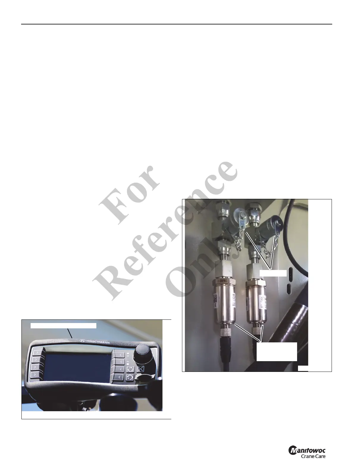
Piston and Rod Pressure Transducers – The piston and
rod pressure transducers (Figure 2-4) measure crane
hydraulic load. They are attached to the rod and piston side
lift cylinders. The transducers are located in the interior
frame gusset under the turret and feature test ports to use
when bleeding air from the hydraulic hoses when calibrating
the transducers. Contact Manitowoc Crane Care for more
information about calibrating RCL sensors.
QScale Operator Console
FIGURE 2-3
9357
Piston and Rod
Pressure
Transducers
Tes t P or ts
FIGURE 2-4
9358
Fo
r
Reference
Only

 Loading...


