Home
Midea
Air Conditioner
MHC-V4W/D2N8-B
Midea MHC-V4W/D2N8-B Engineering Data
5
of 1
of 1 rating
113 pages
Give review
Manual
Specs
To Next Page
To Next Page
To Previous Page
To Previous Page
Loading...
M thermal Mono
104
20200
5
Midea M thermal Mono Engineering Data Book
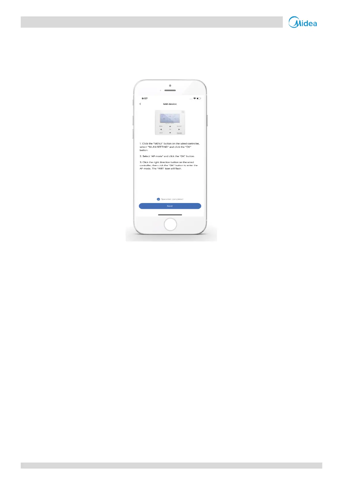
9.2.3
Add Home App
liances
Choose the wi
red con
troller model, t
hen go to add
the devic
e.
Figure 3
-
8.5
: APP con
nection prompts
Opera
te the wir
ed cont
rolle
r according
to APP prom
pts.
W
ait for t
he home appl
iance to c
onnect, and click “
Finish
”.
Midea CAC Confidential
104
106
Table of Contents
Contents
2
Table of Contents
4
General Information
4
System Schematic
5
System Configurations
6
Heat Pump Only
6
Heat Pump and Backup Electric Heater
6
Heat Pump with Auxiliary Heat Source
6
M Thermal Mono Unit Capacity Range and Unit Appearances
7
Unit Capacities
7
Nomenclature
7
Selection of Outdoor Units
8
Selection Procedure
8
Total Heat Load Calculation
8
System Design and Unit Selection
8
M Thermal Leaving Water Temperature (LWT) Selection
9
Optimizing System Design
9
Application 1
10
Typical Applications
10
AHS (Auxiliary Heat Source) Control
11
Domestic Water Heating
11
Space Heating
11
TBH (Tank Booster Heater) Control
11
Application 2
12
Application 2-One Zone Control
12
One Zone Control
12
The Circulation Pumps Operation
12
Mode Set Control
13
Double Zone Control
14
The Circulation Pump Operation
15
Engineering Data
16
MHC-V4(6, 8,10)W/D2N8-B Specifications
17
Specifications
17
MHC-V12(14, 16)W/D2N8-B Specifications
18
MHC- V12(14, 16)W/D2RN8-B Specification
19
Dimensions and Center of Gravity
20
MHC-V12( 14,16)W/D2(R)N8 Dimensions and Center of Gravity
21
Piping Diagrams
22
MHC-V8(10)W/D2N8-B0 Piping Diagram
23
MHC-V4(6, 8, 10)W/D2N8-B Wiring Diagram
24
Wiring Diagrams
24
MHC-V12(14, 16)W/D2N8-B Wiring Diagram
26
MHC-V12(14, 16)W/D2RN8-B Wiring Diagram
28
Capacity Tables
30
Heating Capacity Tables
30
MHC-V4W/D2N8-B Heating Capacity
30
MHC-V6W/D2N8-B Heating Capacity
33
MHC-V8W/D2N8-B Heating Capacity
36
MHC-V10W/D2N8-B Heating Capacity
39
MHC-V12W/D2N8-B MHC-V12W/D2RN8-B Heating Capacity
42
MHC-V14W/D2N8-B MHC-V14W/D2RN8-B Heating Capacity
45
MHC-V16W/D2N8-B MHC-V16W/D2RN8-B Heating Capacity
48
Cooling Capacity Tables
51
MHC-V4W/D2N8-B Cooling Capacity
51
Cooling Operating Limits
58
Heating Operating Limits
58
Operating Limits
58
Abbreviations
59
Domestic Hot Water Operating Limits
59
Hydronic Performance
60
MHC-V12( 14,16)W/D2(R)N8 Hydronic Performance
60
MHC-V4(6, 8, 10)W/D2N8-B Hydronic Performance
60
Overall
61
Sound Levels
61
Sound Pressure Level Measurement (Unit: MM)
61
Sound Pressure Levels
61
MHC-V4W/D2N8-B Octave Band Levels
62
MHC-V6W/D2N8-B Octave Band Levels
62
Octave Band Levels
62
MHC-V10W/D2N8-B Octave Band Levels
63
MHC-V8W/D2N8-B Octave Band Levels
63
MHC-V12W/D2N8-B Octave Band Levels
64
MHC-V14W/D2N8-B Octave Band Levels
64
MHC-V12W/D2RN8-B Octave Band Levels
65
MHC-V16W/D2N8-B Octave Band Levels
65
MHC-V14W/D2RN8-B Octave Band Levels
66
Standard Accessories
67
Installation and Field Settings
68
Notes for Installers Boxes
69
Precautions
69
Preface to Part 3
69
Acceptance and Unpacking
70
Hoisting
70
Installation
70
Installation Room Illustration
71
Placement Considerations
71
Strong Wind Installation
71
Strong Wind Installation Direction
71
Base Structure
72
Cold Climate Installation
72
Hot Climate Installation
72
Outdoor Unit Typical Concrete Base Structure Design (Unit: MM)
72
Drainage
73
Minimum Spacing from Obstacles in Front of the Unit
73
Spacing
73
Stacked Installation
73
Installation in Rows
74
Installation with Obstacles Behind the Unit
74
Single Row Installation
74
Single Row Installation Spacing Requirements
74
Expansion Vessel Pre-Pressure Adjustment
75
Water Circuit Checks
75
Water Pipework
75
Water Volume and Expansion Vessel Pre-Pressure Checks
75
Maximum Water Volume
76
Water Circuit Connection
76
Ethylene Glycol
77
Propylene Glycol
77
Water Circuit Anti-Freeze Protection
77
Adding Water
78
Water Flow Switch
78
Water Piping Insulation
78
Electrical Wiring
79
General
79
Wiring Hole for 4/6Kw Models
79
Wiring Hole for 8~16Kw Models
79
Guidance
80
Secure the Wiring in the Order Shown below
80
Wiring Overview
80
Wiring Overview for 4/6Kw Models
80
Wiring Overview for 8/10/12/14/16Kw Models
81
Wiring Requirements
82
DIP Switch Settings
83
Internal Circulation Pump
83
Introduction
84
User Interface Field Settings
84
Menu Structure
85
DHW MODE SETTING Menu
86
DHW MODE SETTING Menu Overview
86
FOR SERVICEMAN Menu
86
DHW Mode Operation
87
Dt5_On
87
T4DHWMAX and T4DHWMIN
87
DHW Tank Disinfection
88
Operation in DHW PRIORITY
88
COOL MODE SETTING Menu
89
Dtsc
89
T4Cmax, T4Cmin
89
Dtsh
90
HEAT MODE SETTING Menu
90
AUTO MODE SETTING Menu
91
T4Autocmax, T4Autocmin
91
Only Set ROOM TEMP to YES
92
Only Set WATER FLOW TEMP to YES
92
TEMP. TYPE SETTING Menu
92
ROOM THERMOSTAT Menu
93
OTHER HEATING SOURCE Menu
94
OTHER HEATING SOURCE Menu Overview
94
T4_Ahs_On
94
T4_Ibh_On
94
HOLIDAY AWAY SETTING Menu
95
Restore Factory Settings
95
RESTORE FACTORY SETTINGS Screens
95
SERVICE CALL Menu
95
Exit Air Purge Screen
96
POINT CHECK Menu
96
Test Run
96
TEST RUN Menu Overview
96
AIR PURGE Operation
97
Circulation Pump Running
97
Cool Mode Running
97
COOL MODE RUNNING Display
97
Dhw Mode Running
98
DHW MODE RUNNING Display
98
Heat Mode Running
98
HEAT MODE RUNNING Display
98
Preheating for Floor
99
Preheating for Floor Menu
99
Special Function
99
SPECIAL FUNCTION Menu Overview
99
Floor Drying up
100
FLOOR DRYING up Menu
100
FLOOR DRYING up Settings
100
Preheating for Floor Screens
100
Auto Restart
101
Input Define
101
INPUT DEFINE Menu
101
Power Input Limitation
101
Operation Parameter
102
Network Configuration Guidelines
103
RESTORE WLAN SETTING Menu
103
Wired Controller Setting
103
WLAN Setting Menu
103
Add Device
104
Install APP
104
Mobile Device Setting
104
Sign in
104
Add Home Appliances
105
APP Connection Prompts
105
Failed Connection
106
Successful Connection
106
Climate Related Curves
107
Low Temperature Curves for Heating Mode
107
WEATHER TEMP. SET Menu
107
High Temperature Curves for Heating Mode
108
Low Temperature Curves for Cooling Mode
108
Automatic Setting Curve for Cooling Mode
109
Automatic Setting Curve for Heating Mode
109
High Temperature Curves for Cooling Mode
109
Error Code Table
110
Other manuals for Midea MHC-V4W/D2N8-B
Service Manual
113 pages
5
Based on 1 rating
Ask a question
Give review
Questions and Answers:
Need help?
Do you have a question about the Midea MHC-V4W/D2N8-B and is the answer not in the manual?
Ask a question
Midea MHC-V4W/D2N8-B Specifications
General
Brand
Midea
Model
MHC-V4W/D2N8-B
Category
Air Conditioner
Language
English
Related product manuals
Midea MHC-V6W/D2N8-B
113 pages
Midea MHC-V8W/D2N8-B
113 pages
Midea MHC-V22W/D2RN8
93 pages
Midea MHC-V10W/D2N8-B
113 pages
Midea MHC-V12W/D2N8-B
113 pages
Midea MHC-V14W/D2N8-B
113 pages
Midea MHC- V30W/D2RN8
93 pages
Midea MHC-V16W/D2N8-B
113 pages
Midea MHC-V12W/D2RN8-B
113 pages
Midea MHC-V16W/D2RN8-B
113 pages
Midea MHC - V18W/D2RN8
93 pages
Midea MHC-96HWD1N1(A)
87 pages
 Loading...