Technical Information
30
CVA615 Coffee System
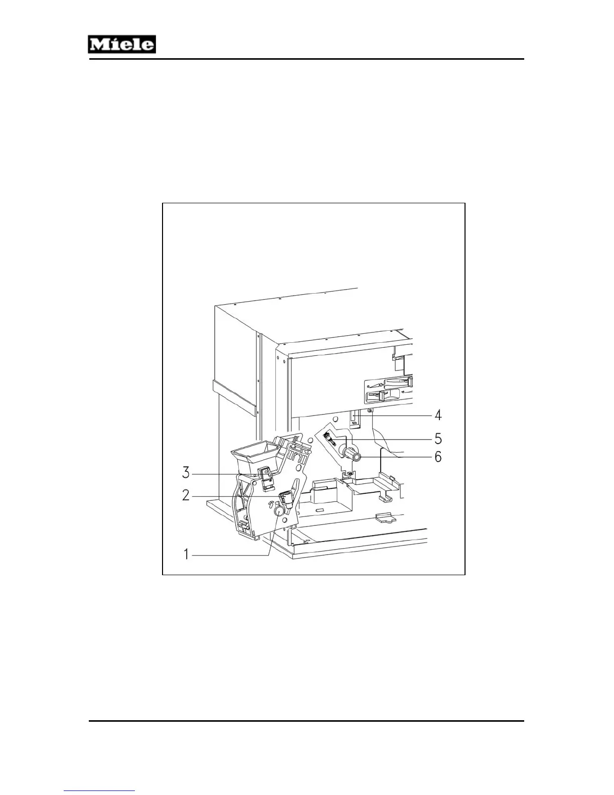
4.15 Brew Unit Drives
Refer to figure 4-17.
When the brew unit is placed in the appliance, it locks into position.
The locking mechanism switch lug (Item 3) activates the brew unit
present switch (Item 4). The drive shaft, (Item 6) engages with the
drive shaft socket,
Figure 4-17: Components of the Brew Unit Drive Assembly, Water
Connection and Present Switch.
1 Brew unit drive shaft socket
2 Socket
3 Locking mechanism switch lug
4 Switch – Brew unit present switch
5 Nozzle – Coffee heater
6 Drive shaft
 Loading...