Home
Milnor
Washer
42 Series
Milnor 42 Series User Manual
4
of 1
of 1 rating
137 pages
Give review
Manual
Specs
To Next Page
To Next Page
To Previous Page
To Previous Page
Loading...
98
Pellerin
Milnor
Corporation
Legend
B...
Cylinder
doors,
see
BPWVUD02
Cylinder
Assembly
2
Sheets
42044WP3,
42044WP3
SM,
42044SP3
BPWD4D01
/
2020273
BPWD4D01.1
0000296533
A.3
6/30/20
4:51
PM
Released
Shell
and
Door
Assemblies
99
101
Table of Contents
Table of Contents
3
General Service Information
8
Limited Standard Warranty
9
How to Get the Necessary Repair Components
10
Trademarks
10
Table 1 Trademarks
10
Safety - Divided Cylinder and Staph Guard
11
Safety Alert Messages-Internal Electrical and Mechanical Hazards
11
Safety Alert Messages-External Mechanical Hazards
11
Safety Alert Messages-Cylinder and Processing Hazards
11
Safety Alert Messages-Unsafe Conditions
12
Damage and Malfunction Hazards
12
Hazards Resulting from Inoperative Safety Devices
12
Hazards Resulting from Damaged Mechanical Devices
13
(See also Service Hazards Throughout Manuals)
14
Careless Operation Hazards-Vital Information for Operator Personnel (See also Operator Hazards Throughout Manual)
14
Careless Servicing Hazards-Vital Information for Service Personnel
14
Careless Use Hazards
14
Torque Requirements for Fasteners
15
Torque Values
15
Fasteners Made of Carbon Steel
15
Figure
15
Table 2 Torque Values for Standard Fasteners with Maximum 5/16-Inch Diameters and no Lubricant
15
Table 3 Torque Values for Standard Fasteners Larger than 5/16-Inch Diameters and no Lubricant
15
Without a Threadlocker
15
Table 4 Torque Values for Plated Fasteners with Maximum 5/16-Inch Diameters and no Lubricant
16
Table 5 Torque Values for Plated Fasteners Larger than 5/16-Inch Diameters and no Lubricant
16
Table 6 Threadlocker by the Diameter of the Bolt (See below Note )
17
Table 7 Torque Values if You Apply Loctite 222
17
With a Threadlocker
17
Table 10 Torque Values if You Apply Loctite 272 (High-Temperature)
18
Table 8 Torque Values if You Apply Loctite 242
18
Table 9 Torque Values if You Apply Loctite 262
18
Stainless Steel Fasteners
19
Table 11 Torque Values if You Apply Loctite 277
19
Table 12 Torque Values for Stainless Steel Fasteners 5/16-Inch and Smaller
19
Table 13 Torque Values for Stainless Steel Fasteners Larger than 5/16-Inch
19
Preparation
20
How to Apply a Threadlocker
20
Figure 2 Apply Threadlocker in a Blind Hole
20
Blind Holes
21
Figure 3 Apply Threadlocker in a through Hole
21
Figure 4 Use Heat for Disassembly of Fasteners with Threadlocker
21
Through Holes
21
General Assembly
22
4231 & 4244Wp2/Wp3
22
Table 14 Parts List-General Assembly 4231 & 4244WP2/WP3
28
Safety-Related Components & Assemblies
29
Safety Placard Use and Placement
30
42044Wp2 & Np2 Single Motor Drive
30
Table 15 Parts List-Safety Placard Use and Placement 42044WP2 & NP2 SINGLE MOTOR DRIVE
31
Safety Placard Use and Placement ISO
32
42044Wp2 & Np2 Single Motor Drive
32
Table 16 Parts List-Safety Placard Use and Placement ISO 42044WP2 & NP2 SINGLE MOTOR DRIVE
33
Vibration Safety Switch Adjustments
34
What the Vibration Safety Switch Does
34
Adjustments
34
Table 17 Effect of Tripping Vibration Safety Switch
34
Figure 5 Vibration Switch
35
Vibration Safety Switch
36
Table 18 Parts List-Vibration Safety Switch
36
Drive Assemblies
37
Drive Chart 4244WP2 SM
38
Table 19 Parts List-Drive Chart 4244WP2 SM
39
Drive Base Installation 4244WP2 SM (Single Motor)
40
Table 20 Parts List-Drive Base Installation
45
Jackshaft 4244WP2 SM
46
Table 21 Parts List-Jackshaft 4244WP2 SM
47
Brake Assembly
48
4244Wp2/Wr2, 4244Sp2/Sr2
48
Figure 6 Exploded View of the Caliper and Repair Kit Components
49
Table 22 Parts List-Brake Assembly 4244WP2/WR2, 4244SP2/SR2
49
Drive Pulley and Belt Maintenance
51
Pulley Requirements
51
Condition of Grooves on Pulleys
51
Figure 7. Examples of Drives this Instruction Applies To: One or more V-Belts, Attached V-Belts and Tooth Belts
51
Figure 8 Pulley Groove Condition
52
Figure 9 Pulley and Shaft Position
52
Pulley and Shaft Position
52
Figure 10 Run-Out
53
Keep Run-Out in Tolerance
53
Belt Requirements
54
Condition of Belts
54
Figure 11 Typical Pulley Assembly
54
Figure 12 Types of Belt Damage
55
Tension of Belts
55
The Pulleys Must Stay Aligned When You Adjust the Belt Tension
56
How to Do Maintenance on Pulleys and Belts
56
Figure 13 a Tension Mechanism that will Not Change the Angle of the Pulleys
56
Figure 14 some Pairs of Tension Mechanisms that Can Change the Angle of the
56
Table 23 Typical Tools for Pulley and Belt Maintenance
56
Typical Steps to Replace Pulleys and Belts
57
Examples of Procedures Used at the Milnor ® Factory to Align Pulleys
58
Figure 15 Use a Straight Edge, a String, or a Laser to Make Sure that All Pulleys Are in the same Plane
58
Figure 16 Use a Level to Make Sure that the Pulleys Are at the same Slope
59
Figure 17 Dial Indicator Used to Find the Axial and Radial Run-Out of a Pulley
59
Bearing Assemblies
60
Main Bearing and Seal Replacement for Divided Cylinder Machines
60
Figure 18 Cross Section View of Front and Rear Bearing Assemblies (Bearing Assembly for 60" and 72" WED Shown. Others Similar.)
61
Removing the Bearing (Front or Rear)
62
Figure 19 Connection from Hydraulic Pump to Assist in Bearing Removal
62
(Front or Rear)
63
Figure 20 Two Bearing Housing Guide Rods in Position
63
Figure 21 Bearing Housing Pulling Fixture in Position
63
Precautions for Bearing Replacement
64
Replacing the Bearing Housing, Seal Sleeve, and Seals (Front or Rear)
64
Figure 22 Installing Seals in Bearing Housing
65
Figure 23 Installing Seal Sleeve in Bearing Housing
65
Figure 24 Installing the Bearing Housing Setting Fixture Onto Housing (42" Ma- Chine Shown)
66
Figure 25 Pushing the Bearing Housing into the Shell
66
Figure 26 Tightening the Bearing Housing into the Shell (42" Machine Shown)
66
Measuring Unmounted Clearance and Setting Bearing (Front or Rear)
67
Figure 27 Measuring Bearing Unmounted Clearance
68
Table 24 Table of Bearing Clearances
68
Tightening Bearing(S) (Front And/Or Rear)
69
Figure 28 Tightening the Bearing Lock Nut (42" Machine Shown)
70
Figure 29 Measuring the Mounted Internal Clearance of the Bearing
70
Main Bearing Assembly
72
Dp3
72
Table 25 Parts List-Main Bearing Assembly 42031, 42044 CP2/CP3, NP2/NP3, WP2/WP3, SP2/SP3, DA2/DA3, DP2/DP3
74
Autospot Installation
76
4244Wp2 Sm
76
Table 26 Parts List-Autospot Installation 4244WP2 SM
77
Frame, Pivots, and Suspension
78
Suspension Adjustments for Divided Cylinder Machines
78
How Shell Adjustments Are Made
78
Shell Hanging Dimensions and Adjustment Procedures
79
Figure 30 Hydro-Cushion™ Upper Shaft and Adjusting Nuts
79
Figure 31 Shell Hanging for Divided Cylinder Machines (Left Side View of 60044WE Shown)
80
Table 27 Hanging Dimensions
80
Push-Down Travel Dimensions and Adjustment Procedures
81
42" Divided Cylinder Machines
81
60" Divided Cylinder Machines
82
Ring Weldments
83
Hold down Adjustment
84
6044Sr2/Sr3, 6044Wr2/Wr3, 72044Sr2/Sr3, 72044Wr2/Wr3
84
Table 28 Parts List-Hold down Adjustment 6044SR2/SR3, 6044WR2/WR3, 72044SR2/SR3, 72044WR2/WR3
85
Suspension Cylinder Assemblies
86
Table 29 Parts List-Suspension Cylinder Assemblies
87
Suspension Cylinder Locations
90
Shell and Door Assemblies
92
Shell Doors
93
42031/42044Cp2,Np2,Wp2,Wp3,Sp2,Sp3, 4244Sp2 Sm
93
Table 30 Parts List-Shell Doors 42031/42044CP2,NP2,WP2,WP3,SP2,SP3, 4244SP2 SM
94
Door Latch
96
Table 31 Parts List-Door Latch
96
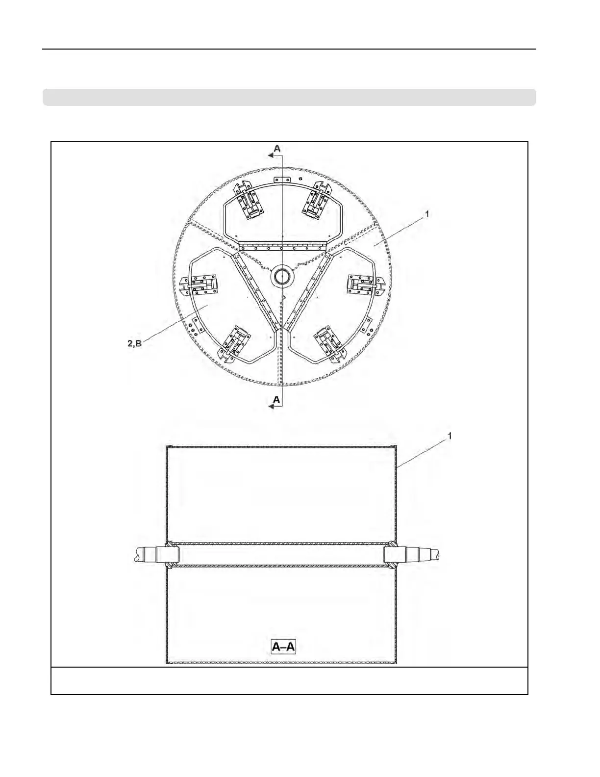
Cylinder Assembly
98
42044Wp2, Np2, Cp2, Sp2
98
Cylinder Assembly
100
Cylinder Doors
102
Sp2 Sm
102
Control and Sensing Assemblies
104
Excursion Switch
105
4244Sp2 Sm
105
Air Chamber Level Switch
106
42044Wr2,Wr3,Sr2,Sr3; 6044Wr2,Wr3,Sr2, Sr3; 72044Wr2
106
Wr3, Sr2, Sr3
106
Temperature Probe
107
42044Sr2, 42044Wr2
107
Chemical Supply Devices
108
Supply Injector Assembly
110
4244Wp2/Wp3, 4244Wp2 Sm, 4244Sp2/Sp3, 4244Sp2 Sm
110
Water and Steam Piping and Assemblies
112
Water & Steam Schematics
114
42044Wp2/Cp2/Np2
114
Water Inlets
116
4244Wp2/Wp3, 4244Wp2 Sm, 4244Sp2/Sp3, 4244Sp2 Sm
116
Flushing Water Supply
120
4244Wp2/Wp3, 4244Wp2 Sm, 4244Sp2/Sp3, 4244Sp2 Sm
120
Servicing Air Cylinders
122
Using Threaded Rods
122
Steam Inlet
124
4244Wr2/Wr3
124
42044Wr2/Wr3/Sr2/Sr3; 60044Wr2/Wr3/Sr2/Sr3
128
8"X10" Stainless Dump Valve
129
10 Pneumatic Piping and Assemblies
131
42044Wp2/Wp3/Cp2/Cp3/Np2/Np3
132
Schematic Diagram
132
Schematic Diagram Continued
133
Brake Air Cylinder
136
Other manuals for Milnor 42 Series
Installation
68 pages
Maintenance Guide
129 pages
4
Based on 1 rating
Ask a question
Give review
Questions and Answers:
Need help?
Do you have a question about the Milnor 42 Series and is the answer not in the manual?
Ask a question
Milnor 42 Series Specifications
General
Brand
Milnor
Model
42 Series
Category
Washer
Language
English
Related product manuals
Milnor 42026
34 pages
Milnor 42044WR2
137 pages
Milnor 42030V6Z
110 pages
Milnor 42026V6Z
110 pages
Milnor 42026V6J
117 pages
Milnor 42026X7J
165 pages
Milnor 48040H7K
49 pages
Milnor 48040M7K
49 pages
Milnor 42044SR2
137 pages
Milnor 42044 WR2
81 pages
Milnor 42026V6J/V6W
118 pages
Milnor 42030V Series
34 pages