F3Ci Service Manual
_______________________________________________________________________________________________________________________
22
•
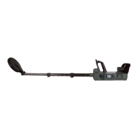
Reattach the armrest with four screws (12mm).
•
Check all moving parts for correct operation.
•
Insert batteries, turn on the detector then conduct mechanical & functional testing
as described in Section 2 Mechanical & Functional Testing.
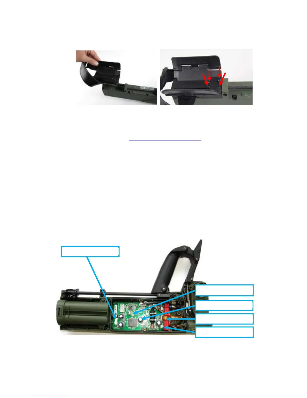
3.3 Main Printed Circuit Board (PCB)
a.
The main PCB of the F3Ci is a line replaceable unit and this section of the manual
describes the procedure for its replacement. Figure 28 shows the main parts associated with the
main PCB.
b. 3004-0133 Main PCB Kit, is a service kit containing the main PCB and the associated parts,
when a replacement main PCB is required this part number should be ordered.
Note
Repairs to and disassembly of the main PCB are not detailed in this manual. Repairs to the
main PCB should only be conducted by authorised Minelab Engineers.
 Loading...