F3Ci Service Manual
_______________________________________________________________________________________________________________________
54
•
Take note of the orientation of the switches and the ribbon cable and use a 10mm
spanner to remove the nut and locking washer from both switches.
c. The control switches can now be removed and replaced.
Note
Use care handling the control switches and the flexible ribbon cable. These are internal
components and will be easily damaged if they are forced or misaligned.
Note
Do not use a soldering iron on the switches or the flexible ribbon cable.
•
Check each control switch has a clean and lightly greased O-ring correctly positioned
on the mounting face.
•
Carefully align the control switches and the flexible ribbon cable within the detector
body as illustrated in Figure 91.
•
Insert the control switches into the detector body, fit the lock washer and 10mm nut.
•
Fit the switch knob then the spring followed by the bush and screw to the control
switch.
•
Check the switch knobs move through their arc of movement with end stops.
•
Identify the connector on the interface PCB that mates with the flexible ribbon cable
of the control switches. Open the connector locking bail (slide out). As shown in
Figure 89.
•
Insert the ribbon cable into the connector on the interface PCB then close the locking
bail on the connector. Also see Installing the Main PCB, figure 44.
d.
Reassemble the detector by closing the detector body as described in Section 3.2 -
Closing the Detector Body.
O-Ring
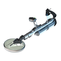
Figure 91: Control Switches
 Loading...