−37−−36−
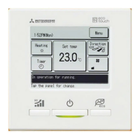
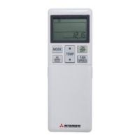
・ When auto-off is enabled
The unit will enter the
“
Operation wait
”
state when an hour has elapsed since the last time a human presence was detected and
will be in
“
Complete stop
”
state after another 12 hours.
"Operation wait"... The unit stops but will resume operation when human presence is detected.
When the unit is in
“
Complete stop
”
,
“
In auto-off mode
”
will be displayed on the message display.
"Complete stop"... When auto-off is enabled, the unit stops.
The unit will not resume operation even when human presence is detected.
The message
“
In auto-off mode
”
will disappear from the message display, and the operation lamp will turn off.
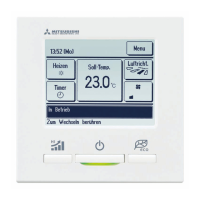
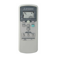
・When power control is enabled
The amount of human motion is detected by a motion sensor to adjust the Set temp.
During power control,
“
Power control ON
”
will be displayed on the message display.
Menu
Direction
Heating
20:20
(Tue)
F1: High power F2: Energy-saving
Timer
Power control ON
Set temp
Menu
Direction
Cooling
16:32
(Mon)
F1: High power F2: Energy-saving
Timer
In auto-off mode
Set temp
1
Tap the
Menu
button on the TOP screen and select
Useful functions
⇒
Individual ap control
, or tap the
Change ap direction
button on the TOP screen and
select
Ind. ap control
, and then enter the administrator password.
When one IU is connected to the R/C:
☞
3
When two or more IUs are connected to the R/C:
☞
2
Motion range (upper
, lower, left, or right limit positions) of the ap at each blow outlet can be set to a desired range.
■When the R/C is set as the sub R/C, the individual ap control cannot be set.
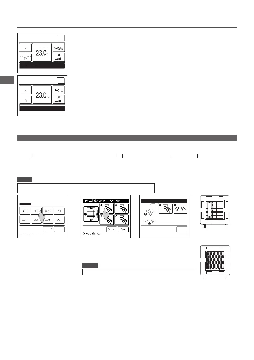
Individual flap control
・Individual ap control should be set when the unit is stopped.
・When you perform Individual ap control while the unit is in operation, the acknowledge screen for unit stop is displayed.
Advice
2
When two or more IUs are
connected to the R/C, a list of IUs is
displayed. Tap the IU to be set.
IU select
Next Back
Select an IU address.
3
Select the number of the ap of which the motion range is changed. (
☞
4 )
■When you perform Individual ap control while the unit is stopped and there are two or more aps at
the blow outlet, such as the FDT type, the ap at blow outlet No. ① will keep moving while the blow
outlet selection screen is displayed. The gure displayed on the screen shows the installed unit
viewed from the oor side. Select the ap based on this gure. When you have selected the blow
outlet, the ap with the number you selected will move.
■You can set all aps at once by tapping the
Bat.set.
button (except for FDKs with a left/right ap).
■When there is only one ap at the blow outlet, such as the ceiling suspended type only the ap that
can be set will be displayed.
For an FDK with a left/right ap, select the upper/lower ap or left/right ap.
When you select the upper/lower ap (
①
):
☞
4
When you select the left/right ap (
②
):
☞
8
Individual ap control Select ap
Back
№④
№②
配管側
制
御
箱
ルーバ№
Pipe side
Control box
Drain hose side
Louver No.
[For FDT]
№④
№②
№③
配管側ドレンホース側
ルーバ№
[FDTCの場合]
№①
Pipe sideDrain hose side
Louver No.
[For FDTC]
・This operation is not performed when individual ap control is set during operation.
Advice
PJZ012A180_EN.indd 36 2019/03/29 11:33:33
 Loading...