−7−−6−
To disassemble the R/C case into the upper and lower pieces after assembling
them once
· Insert the tip of at head screwdriver or the like in the recess at the lower part of
R/C and twist it lightly to remove. It is recommended that the tip of the screwdriver
be wrapped with tape to avoid damaging the case.
Take care to protect the removed upper case from moisture or dust.
In case of embedding wiring
(When the wiring is retrieved “Backward”)
①
Embed the switch box and the R/C wires beforehand.
Seal the inlet hole for the R/C wiring with putty
.
Perform installation and wiring work for the remote controller according to the
following procedure.
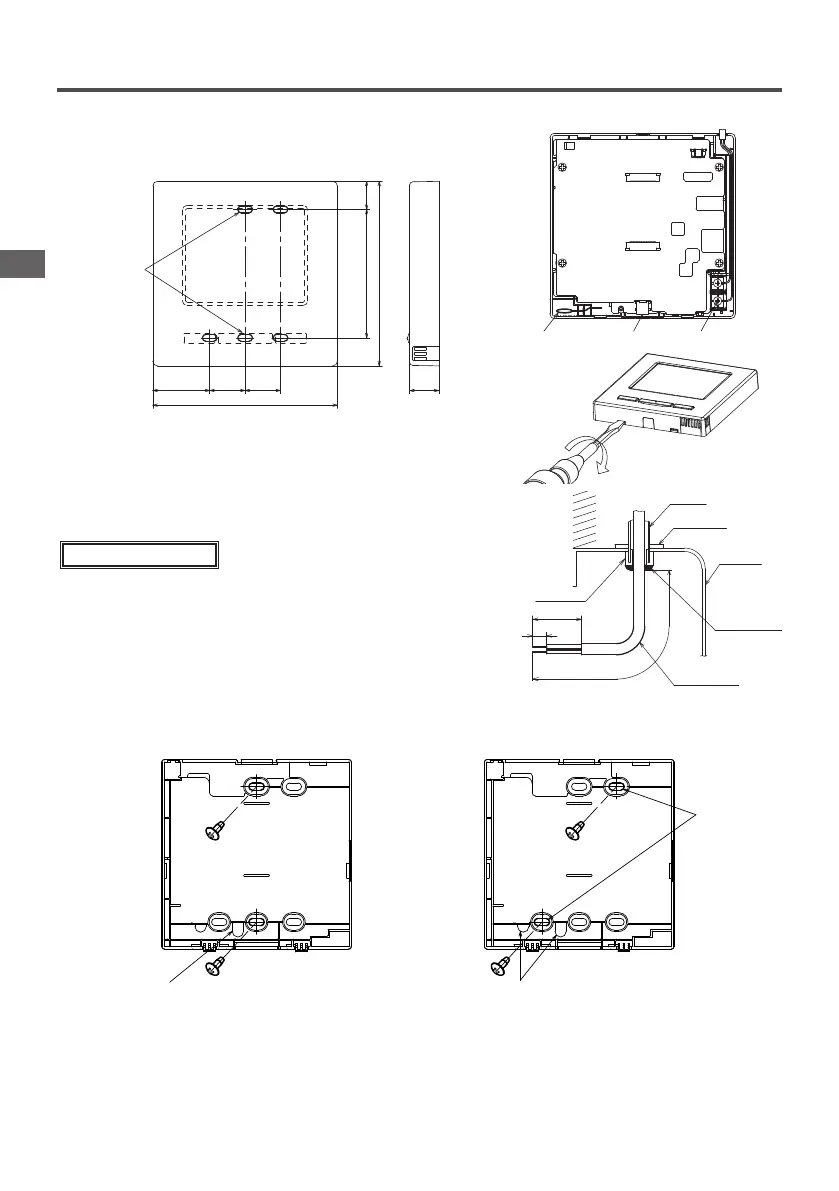
Dimensions (Viewed from front)
37 23 23
固定穴
18.383.5
120
19
120
37 23 23
19
120
Fixing holes
83.5
120
18.3
PCB side (Viewed from rear)
8
50
200
壁
ロ ッ ク ナ ット
スイッチ
ボックス
パテでシール
すること
リモコン 配 線
ブッシ ング
センサー
USB
端子
Wall
Conduit
Sensor USB port Terminal block
Locknut
Bushing
Switch
box
Seal with putty
R/C cable
②
When wires are passed through the bottom case, x the bottom case at 2 places on the switch box.
Switch box for
1 pcs
Switch box for
2 pcs
下
上
下ケース
配線取出口
ねじ取付部の
薄肉部分を
ナイフ等で、
切 りとって
からねじを
し めてくだ
さい 。
Bottom case
Cut out the thin
wall part at the
screw mounting
section with a
knife or the like
before tightening
the screw.
Wire outlet
Downside
Upper side
配線取出口
下
上
下ケース
下
上
下ケース
配線取出口
ねじ取付部の
薄肉部分を
ナイフ等で、
切 りとって
からねじを
し めてくだ
さい 。
Bottom case
Downside
Upper side
Wire outlet
4 . Installation procedure
PJZ012A180_EN.indd 6 2019/03/29 11:33:13
 Loading...