MPI – General
13-3
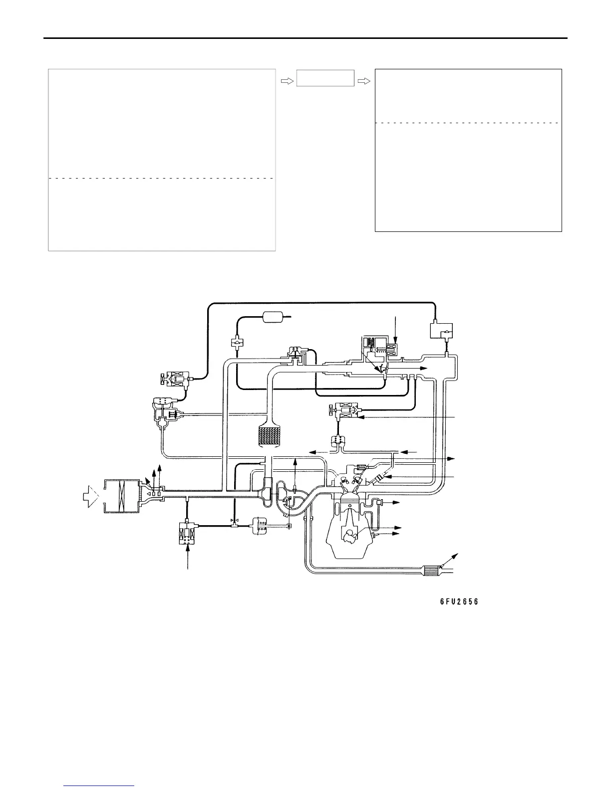
MPI System Diagram
l1 Injector
l2 ISC servo
l3 Fuel pressure control valve
l4 Waste gate solenoid valve
l5 Secondary air control solenoid valve
D Control relay
D Fuel pump relay
D A/C relay
D Ignition coil
D Exhaust temperature warning lamp
D Engine warning lamp
D Diagnosis output
D Alternator G terminal
D Fan motor relay
D Tachometer
D Fuel pump relay No.2
L1 Oxygen sensor
L2 Air flow sensor
L3 Intake air temperature sensor
L4 Throttle position sensor
L5 Idle switch
L6 Camshaft position sensor
L7 Crank angle sensor
L8 Barometric pressure sensor
L9 High temperature sensor
L10 Engine coolant temperature sensor
L11 Detonation sensor
D Power supply voltage
D Ignition switch-IG
D Ignition switch-ST
D Vehicle speed sensor
D A/C switch
D Power steering fluid pressure switch
D Alternator FR signal
Engine ECU
L1 Oxygen sensor
L2 Air flow sensor
L3
Intake air tem-
perature sensor
L4,
L5
L6 Camshaft position
sensor
L7 Crank angle sensor
L8 Barometric
pressure sensor
L9 High temperature
sensor
L10 Coolant temperature sensor
L11 Detonation sensor
l1 Injector
l2 ISC servo
l3 Fuel pressure
control valve
l4 Waste gate
solenoid valve
l5 Secondary air
control solenoid
valve
Canister
Check valve
From
fuel
tank
Throttle position
sensor (with a
built-in
idle
switch)
Secondary
air valve
Air
To fuel
tank
Fuel
pressure
regulator
From
fuel
pump
Waste gate
actuator
Catalytic converter

 Loading...