HEATER AND MANUAL AIR CONDITIONER –
Troubleshooting /
On-vehicle Service
55-6
INSPECTION AT THE AUTOMATIC COMPRESSOR-ECU TERMINAL
Terminal
No.
Check item Checking requirements Normal condition
1 Output from ECU to A/C compressor
A/C compressor relay: OFF System voltage
re
ay
A/C compressor relay: ON 0 V
2 Input from A/C switch to ECU A/C switch: OFF 0 V
A/C switch: ON System voltage
3 Earth Always 0 V
ON-VEHICLE SERVICE
REFRIGERANT CHARGING
Caution
The refrigerant generates toxic gases when it is expored
to a heat source such as fire. Keep flames away from
the refrigerant. Perform refrigerant charging at a
well-ventilated place.
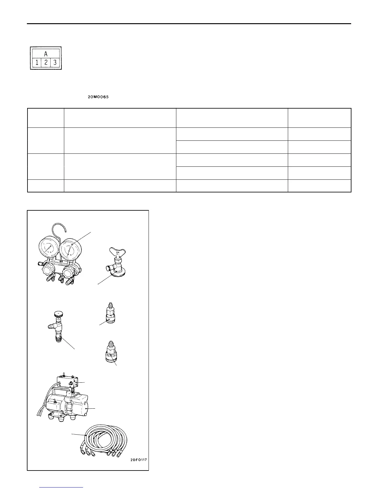
1. Recommended charging tools
The following commercially available tools are recommended
for discharging and charging refrigerant.
D Gas charging set [No. EA95 (R134a)]
D Gas charging set case [No. EA101CS-2]
D Gauge manifold [No. EA101N-1]
D Charging valve [No. EA108N]
D Adapter valve [No. EA104AD-3]
NOTE
The adapter valve opens when the handle is turned
clockwise and closes when it is turned counter-clockwise.
D Quick joint (for low pressure) [No. EA413L]
D Quick joint (for high pressure) [No. EA413H]
D Charging hose (red) [No. EA104N-1]
D Charging hose (blue) [No. EA104N-2]
D Charging hose (yellow) [No. EA104N-3]
D Vacuum pump [No. EA112A]
D Vacuum pump adaptor [No. EA112X]
Gauge manifold
Adapter valve
(for low pressure)
Charging hose
Vacuum
pump adaptor
Quick joint
(for low pressure)
Charging valve
Quick joint
(for high pressure)
Vacuum pump

 Loading...