9
DEVICE EXPLANATION
9.2 Internal User Devices
9.2.5 Annunciator (F)
9
- 14
9
Device Explanation
10
CPU Module Processing
Time
11
Procedure for Writing
Program to CPU Module
AppendicesIndex
9.2.5 Annunciator (F)
(1) Definition
Annunciators are internal relays used for fault detection programs created by the user.
(2) Special relay and special registers at annunciator ON
When annunciators switch ON, a special relay (SM62) switches ON, and the Nos. and
quantity of the annunciators which switched ON are stored at the special registers
(SD62 to 79).
The annunciator No. stored at SD62 is also registered in the "fault history area".
POINT
For the Basic model QCPU, only one annunciator No. is stored into the error
history area while the PLC power is ON.
(3) Applications of annunciators
Using annunciators for a fault detection program, an equipment fault or fault
presence/absence (annunciator number) can be checked by monitoring the special
register (SD62 to 79) when the special relay (SM62) switches ON.
(4) Number of used N/O and N/C contacts
There are no restrictions on the number of contacts (N/O contacts, NC contacts) used
in the program, provided the program capacity is not exceeded.
• Special relay : SM62 • • • • • Switches ON if even one annunciator switches ON.
• Special register : SD62 • • • • • No. of first annunciator which switched ON is stored
here.
SD63 • • • • • The number (quantity) of annunciators which are
ON is stored here.
SD64 to 79 • • • Annunciator Nos. are stored in the order in which
they switched ON.
(The same annunciator No. is stored at SD62 and
SD64.)
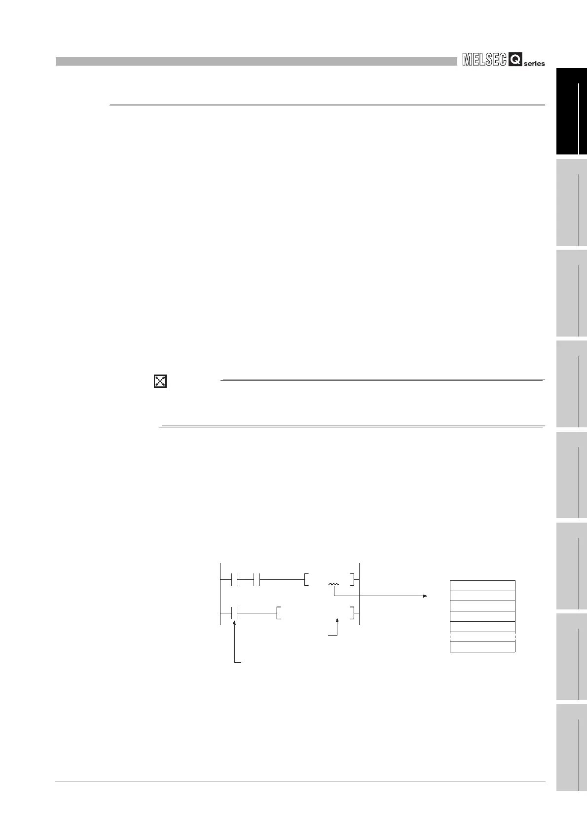
Example
The program which outputs the No. of the ON annunciator (F5).
Diagram 9.11 Detection and storage of annunciator ON
SD62BCDP
SM62
SET
F5
K4Y20
X0
X10
SM62
SD62
SD63
SD64
SD65
SD79
0
0
[Fault detection program]
Output of annunciator
No. which switched ON
Annunciator ON detection
OFF to ON
0 to 5
0 to 1
0 to 5