3Installing the option devices
Installation the motorized hand set (4A-HM02)
3-37
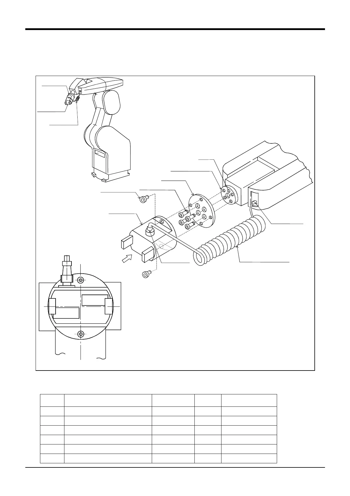
3.3 Installation the motorized hand set (4A-HM02)
Fig. 3-4 shows the construction of the motorized hand set and the installation procedure and Table 3-5 shows the
configuration equipment which correspond with the Fig. 3-4.
Fig.3-4 : Motorized hand set installation procedures
Table 3-5 : Configurations for the motorized hand set.
Number Part name Model type Quantity Notes
<1> Motorozed hand 1A-HM011
<2> Motorozed hand curl cable 1E-GHCD-11
<3> Motorozed hand interface 2A-RZ364 1 Install on controller
<4> Hexagon socket bolts M5x164
<5> Hexagon socket bolts M3x122
<6> Hand adapter BU144D697H011
ViewfromA
φ5hole
Mechanicalinterface
Handadapter
M5×16(4)
Motorizedhand
A
Handconnector
Robotconnector
Motorizedhandcurlcable
M3×12(2)
<5>
<4>
Hexagon socket bolts
Hexagon socket bolts
Motorizedhand
<1><5>
Handadapter
<4><6>
Motorizedhand
curlcable
<2>

 Loading...


