3-36
Installation the pneumatic hand set (4A-HP02/HP02E)
3Installing the option devices
3.2.1 Installing the 1E-HP01/1E-HP01E pneumatic hand
Fig. 3-3 shown the method for installing the pneumatic hand. The installation steps are as folows:
1) Use four M5x16 hexagon socket head bolts <5> to install the head adapter <7> to the robot arm's
mechanical interface.
2) Use four M3x12 hexagon socket head bolts <6> to install the pneumatic hand to the hand adapter. Use Fig.
3-3 to find the where the ends of the cables should be connected to the adapter.
3) As shown in Fig. 3-3, connect the hand curl tubes to coupling "1" and coupling "2", which protrudes from
the cover of the forearm. The opposite end of the tube connected to coupling "1" should be attached to the
hand's OPEN coupling, and the opposite end of the tube connected to coupling "2" should be attached to
the hand's CLOSED coupling.
4) As shown in Fig. 3-3, connect the hand check cable, which is attached to the main unit of the hand, to the
connector CON1H, which protrudes from the cover of the forearm. This completes the installation of the
hand.
3.2.2 Installing the 1E-VD01/1E-VD01E solenoid valve set
To install the solenoid valve set, refer to "3.1Installing the solenoid valve set(1E-VD01/VD01E/VD02/VD02E)" on
page 31 in this manual.
3.2.3 Installing the pneumatic hand interface
To install the pneumatic hand interface, refer to separate manual "CR1 Controller INSTRUCTION MANUAL/
Controller setup, basic operation, and maintenance".
3.2.4 Setting the parameters
For the pneumatic hand (1E-HP01/1E-HP01E), the tool data is 107mm. Refer to separate manual "CR1/CR2/
CR4/CR7/CR8 Controller INSTRUCTION MANUAL/Detailed explanations of functions and operations", and set
the value of the MEXTL parameter to 107mm.
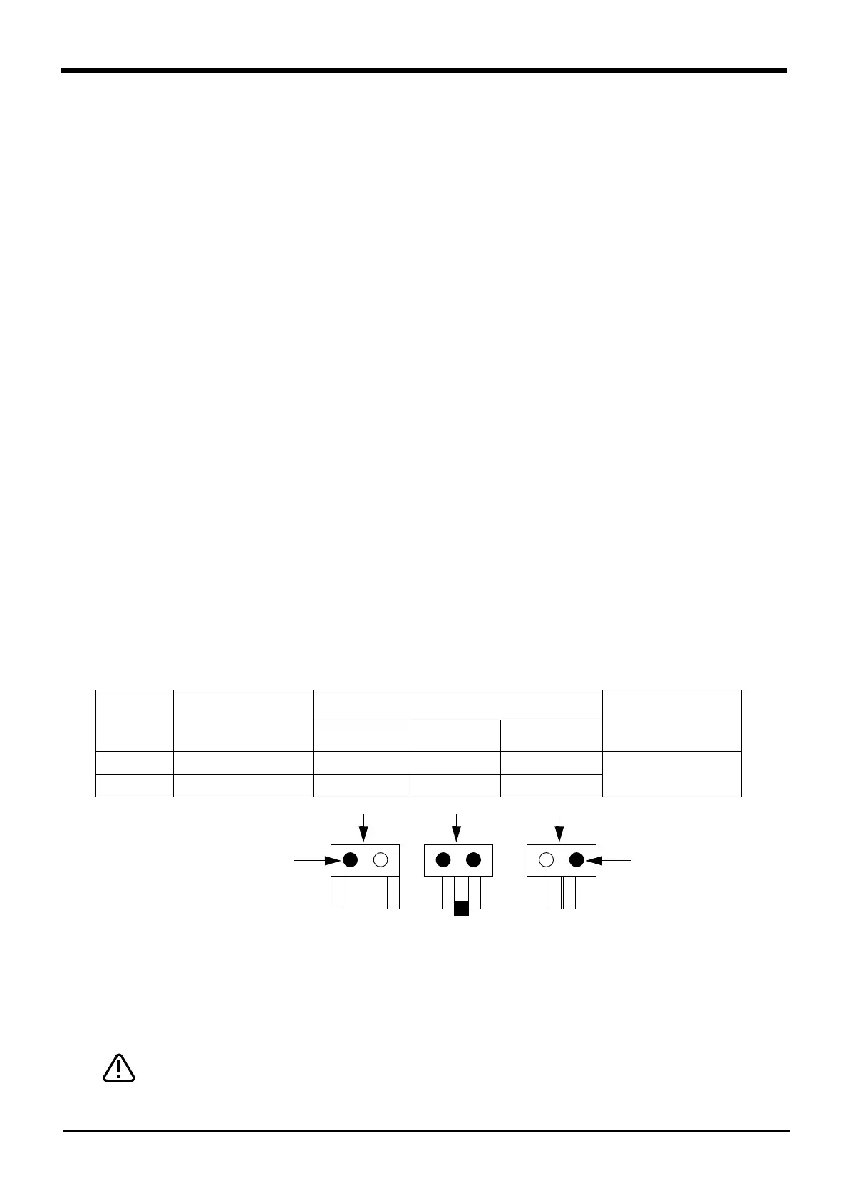
3.2.5 Open/close setting of the hand and settings for input signals
The connections for the optional pneumatic hand sensor, and the bit settings for input signals and for the hands
open/close setting, are shown in Table 3-4. The hand connector numbers have been assigned numbers from the
connector pins located at the end of the forearm.
Table 3-4 : The hand's open/close setting and input signal settings
3.2.6 Confirming operability
1) Operate the teaching pendant to confirm that the hand opens and closes.
2) To operate the teaching pendant, refer to separate manual "CR1/CR2/CR4/CR7/CR8 Controller
INSTRUCTION MANUAL/Detailed explanations of functions and operations".
3) If the open/close settings are reversed, confirm the connection settings with Table 3-1 or Table 3-2 and
reset the settings.
While operating the hand, depending on the J5 axis and J6 axis, the hand curl-tube
and the hand check cable can get entangled with the hand adapter and forearm. In this
case, temporarily remove the hand, and reposition it to its correctly installed position,
as shown in Fig. 3-3.
This completes the installation of the pneumatic hand set.
Hand check
connector
numbers
Signal
Setting pins for the open/close setting of the hand
Comments
Open Half open Closed
1 General purposeinput 900 0 11
Corresponds to hand 1
2 General purposeinput 9011 1 0
Open edge sensor
(General-purpose input 901)
Closed edge sensor
(General-purpose input 900)
CAUTION

 Loading...


