5-78
Resetting the origin
5Maintenance and Inspection
5.5.2 Jig method
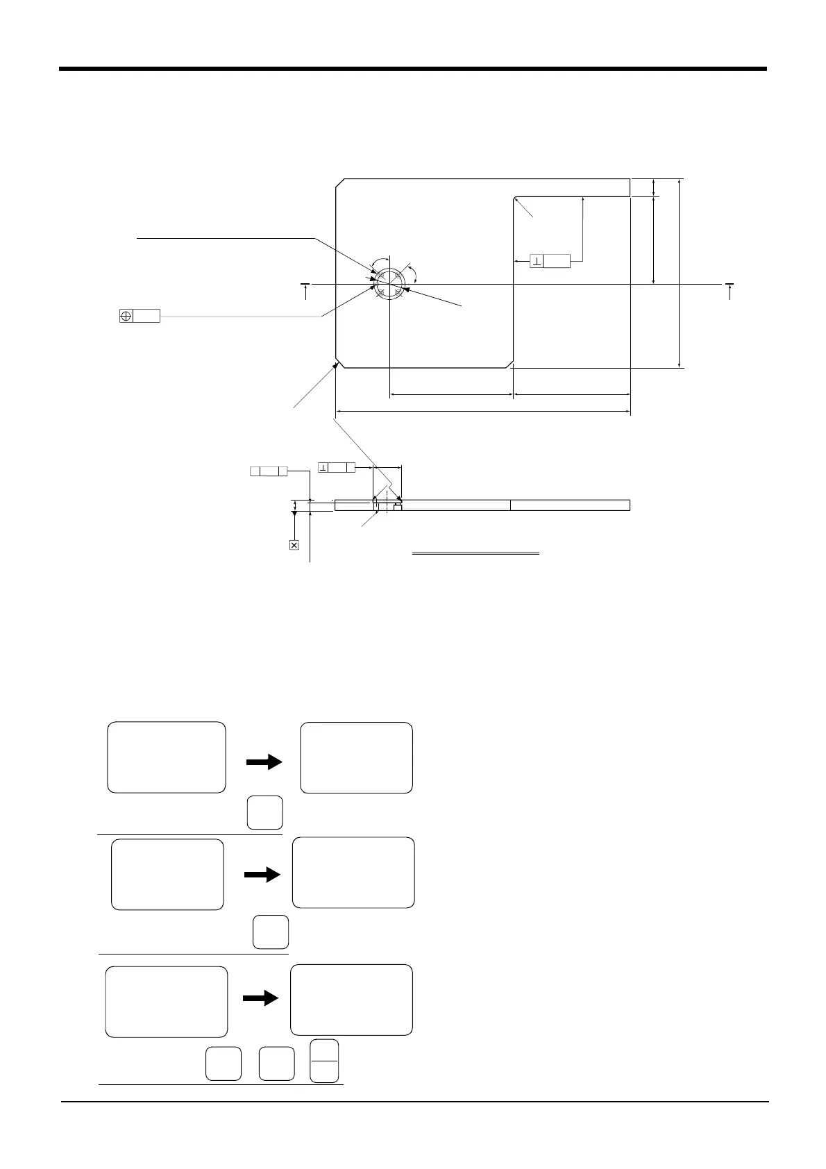
The reference dimension drawing of the calibration jig (1E-INST) used with this method is shown in Fig. 5-20.
This jig is the same option as the Mitsubishi RV-E, RV-EN, RV-4A/5AJ/3AL/4AJL Series.
Fig.5-20 :1E-INST (calibration jig) reference dimension drawing
The procedure of setting the origin with the calibration jig is shown below.
This operation is carried out with the teaching pendant. Set the [MODE] switch on the front of the controller to
"TEACH", and set the [ENABLE/DISABLE] switch on the teaching pendant to "ENABLE" to enable the teaching
pendant.
The following operation is carried out while lightly pressing the deadman switch on the teaching pendant.
1) Press the [5] key on the Menu screen to select
the Maintenance screen.
2) Press the [4] key to select the Origin Setting
screen.
3) Press the [3] key to select the jig method. Then,
press the [1] key and the [INP] key to turn the
servo OFF.
0.04
C1
C0.5
φ40H7
+0.025
0
×
×
0.04
×
〃
14
11.72±0.05
R0.4 or less
6.3a
6.3a
1.6a
Reamer through A-A
0.05
R10
AA
267
122±0.05
25
45゜
φ31.5
174.94±0.05
163
410
0.02
(The standard is in the
center of the Φ40H7)
3-C10
φ5H7
+0.012
0
reamer through
4-5.5 drill through
(equal circumference divisions)
φ11×7 counterbore
(from rear surface)
6.3a
6.3a
<MENU>
1.TEACH 2.RUN
3.FILE 4.MONI
5.MAINT 6.SET
<MAINT>
1.PARAM 2.INIT
3.BRAKE 4.ORIGIN
5.POWER
Select the maintenance screen
+C
(J6)
5
STU
<JIG>
SERVOOFF
OK?(1)
1:EXECUTE
Select the Origin Setting screen
<MAINT>
1.PARAM 2.INIT
3.BRAKE 4.ORIGIN
5.POWER
<ORIGIN>
1.DATA 2.MECH
3.JIG 4.ABS
5.USER
-Y
(J2)
4
MNO
<ORIGIN>
1.DATA 2.MECH
3.JIG 4.ABS
5.USER
Select the jig method
-Z
(J3)
3
JKL
→
-B
(J5)
1
DEF
→
INP
EXE