3Installing the option devices
Installing the solenoid valve set(1E-VD01/VD01E/VD02/VD02E)
3-33
3.1.2 RV-2AM, RV-3AJM (Protection specification)
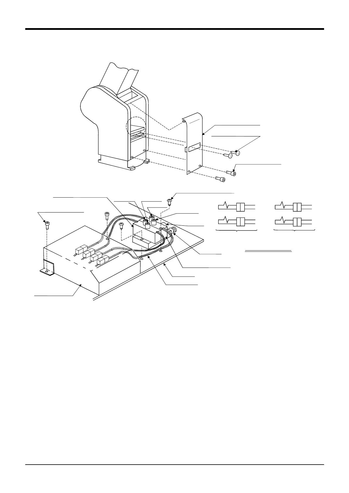
Fig.3-2 : Solenoid valve installation procedures (RV-2AM/3AJM)
1) Remove the two (M3x6) screws <2> and the two (M3x8) bolts <3>, and remove the shoulder cover (B) <1>.
2) Unfasten the two (M3x8) bolts <11> holding the battery cover <12>, and remove the cover.
3) Install the solenoid valve by fastening it with the two attached (M3x25) screws <5> to the screw holes on the
plate <4> of the robot arm.
4) Connect one of the two (φ6) pneumatic hoses in section A --the one marked "AIR IN"-- to the quick
coupling (port P) <9> of the solenoid valve <6>. The primary air flow can now be supplied from the pneumatic
port at the base.
5) Connect the hose marked "1" to port A <7> on the primary solenoid valve <6>.
Connect the hose marked "2" to port B <8> on the primary solenoid valve <6>.
If you are using the double type valves (1E-VD02/VD02E), you need to do the following:
Connect the hose marked "3" to port A <11> on the secondary solenoid valve <10>.
Connect the hose marked "4" to port B <12> on the secondary solenoid valve <10>.
6) Connect the GR1 plug protruding from the primary solenoid valve <6> to the connector GR1.
Connect the GR2 plug protruding from the primary solenoid valve <6> to the connector GR2.
If you are using double type valves (1E-VD02/VD02E):
Connect the GR3 plug protruding from the secondary solenoid valve <10> to the connector GR3.
Connect the GR4 plug protruding from the secondary solenoid valve <10> to the connector GR4.
7) Store the newly attached connectors in the battery cover <12>, and reinstall the battery cover.
8) When you have complered the installation, reinstall the shoulder cover (B) <1> to its original position, and be
careful not to entangle the cables when you do so.
SectionA
<1>Shouldercover(B)
<2>Trussscrew(M3×6)
<3>Socketheadbolt
(M3×8)
GR2
GR1
GR4
GR3
<5>Flatheadscrews(M3×25)
<12>PortB
<12>Batterycover
PortR
<9>PortP
Leadconnector
<4>Plate
<6>Primarysolenoidvalve
<11>PortA
<8>PortB
<7>PortA
Detaileddrawingof
<10>Secondarysolenoid
valve
<11>Socketheadbolt
(M3×8)
Connector connection
GR1
GR2
GR3
GR4
When using one-row
solenoid valve
When using two-row
solenoid valve