6Appendix
Configuration flag
Appendix-85
6 Appendix
Appendix 1 : Configuration flag
The configuration flag indicates the robot posture.
For the 6-axis type robot, the robot hand end is saved with the position data configured of X, Y, Z, A, B and C.
However, even with the same position data, there are several postures that the robot can change to. The posture
is expressed by this configuration flag, and the posture is saved with FL1 in the position constant (X, Y, Z, A, B, C)
(FL1, FL2).
The types of configuration flags are shown below.
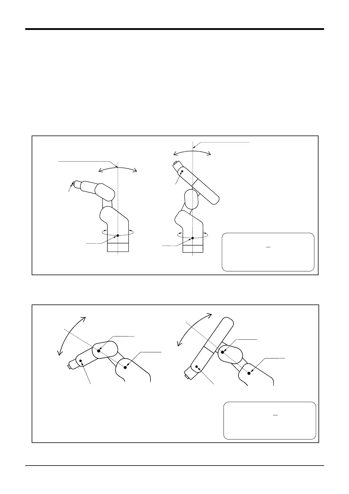
(1) RIGHT/LEFT
P is center of flange in comparison with the plane through the J1 axis vertical to the ground.
Q is center of J5 axis rotation in comparison with the plane through the J1 axis vertical to the ground.
Fig.6-1:Configuration flag (RIGHT/LEFT)
(2) ABOVE/BELOW
Q is center of J5 axis rotation in comparison with the plane through both the J3 and the J2 axis. .
Fig.6-2 : Configuration flag (ABOVE/BELOW)
Rotation center of J1 axis
J1 axis
RIGHT LEFT
Q
Rotation center of J1 axis
J1 axis
RIGHT
LEFT
P
FL 1(Flag 1 )
&B 0000 00
00
↑
1/0= R I GH T / L E F T
Note) "&B" is shows the binary
5-axis type
6-axis type
BOVE
Q
J3axis
J2ax
ABOVE
Q
J3axis
J2ax
FL 1(Flag 1 )
&B 0000 000
0
↑
1/0= ABOV E / B E L OW
Note) "&B" is shows the binary
5-axis type
6-axis type

 Loading...


