3Installing the option devices
Installing the solenoid valve set(1E-VD01/VD01E/VD02/VD02E)
3-31
3 Installing the option devices
3.1 Installing the solenoid valve set(1E-VD01/VD01E/VD02/VD02E)
The following shows how to install the solenoid valve set.
Please note that the installation method differs, depending on the robot arm type. Refer to the item which
corresponds to robot type being used.
3.1.1 RV-2A, RV-3AJ (General environment)
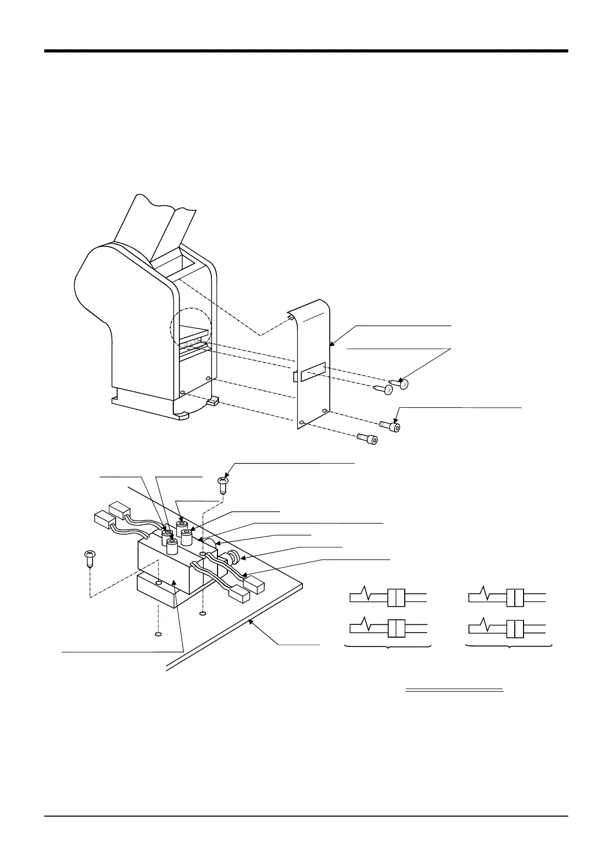
Fig. 3-1:Solenoid valve installation procedures(RV-2A, RV-3AJ)
Fig. 3-1 shows the solenoid valve installation procedures and the solenoid valve connector connection
procedures. The installation procedures are as follow. This work must be carried out with the controller power
turned OFF.
1) Remove the two (M3x6) screws <2> and the two (M3x8) bolts <3>, and remove the shoulder cover (B) <1>.
2) Install the solenoid valve by fastening it with the two attached (M3x25) screws <5> to the screw holes on the
plate <4> of the robot arm.
SectionA
<1>Shouldercover(B)
<2>Trussscrew(M3×6)
<3>Socketheadbolt(M3×8)
GR2
GR1
GR3
GR4
<5>Flatheadscrew(M3×25)
<12>PortB
<10>Secondarysolenoidvalve
PortR
<9>PortP
Leadconnector
<4>Plate
<6>Primarysolenoidvalve
<11>PortA
<8>PortB
<7>PortA
Detaileddrawingof
sectionA
Connector connection
GR1
GR2
GR3
GR4
When using one-row
solenoid valve
When using two-row
solenoid valve

 Loading...


