-
13
-
'16 • SCM-T-199
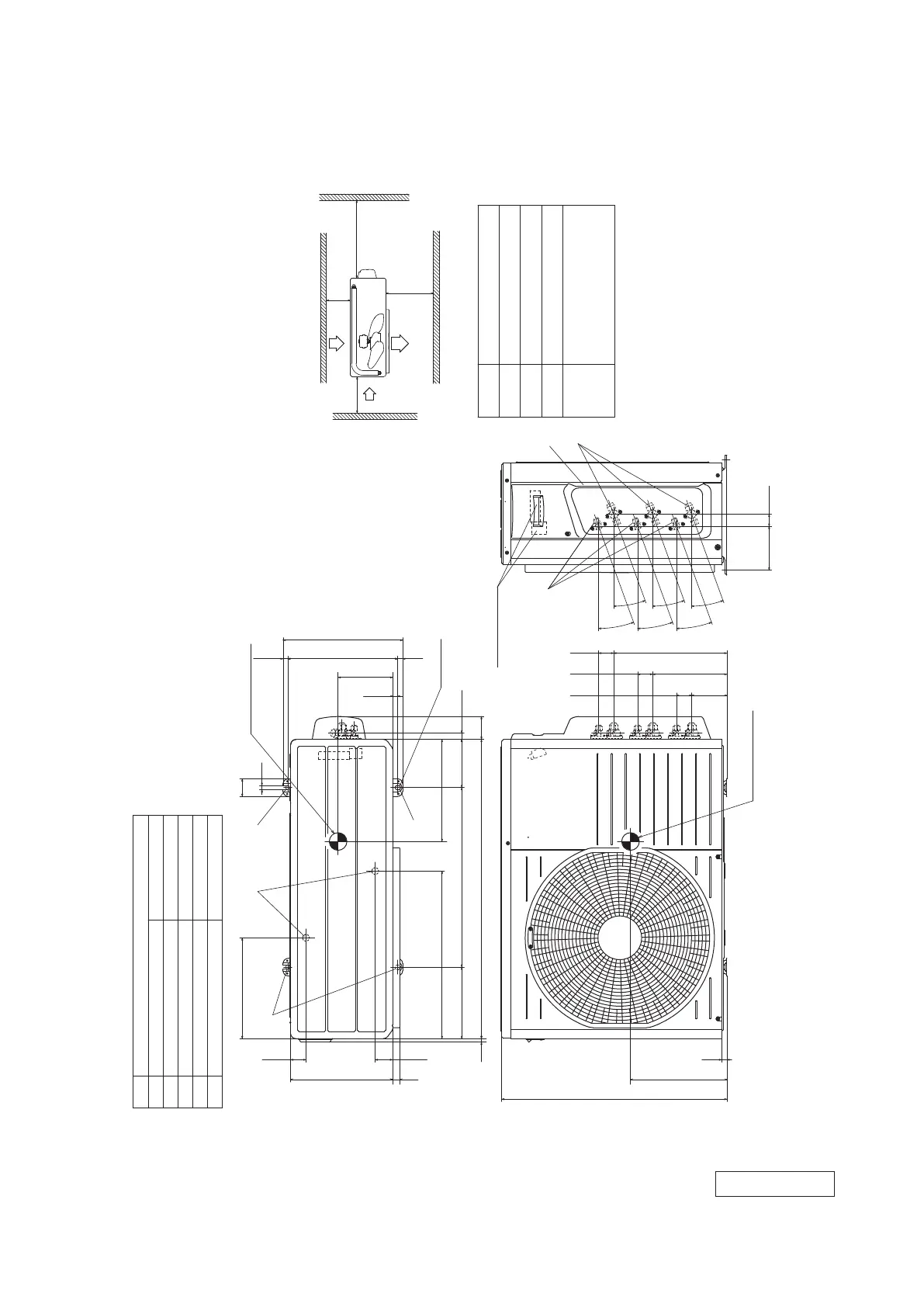
Model SCM50ZS-S
Unit:mm
L2
Inlet
Outlet
Inlet
L3
L1
Service
space
( )
L4
L2
L3
L4
L1
100 or more
100or more
No obstacles
(Service space or
electrical parts)
600 or more
Installation space
φ9.52(3/8")( Flare)
Content
C Pipe/cable draw-out hole
D
E Anchor bolt hole
Drain discharge hole
Symbol
B
A Service valve connection(gas side)
M10-12×4 places
φ20×2 places
Service valve connection(liquid side)
φ6.35(1/4")( Flare)
43.5
286.4
49.6
136.9
14 312.5
50
12
13.5
340
640
15
100.3 42.7
124.1 34.6
211 42.7
20°
20°
20°
20°
321.7 42.7
20°
20°
290
476
203.1 510
850
14.6
2-12x16
17.9
65
274
290
Slot hole
155
21
10
Minimum installation space
Center of gravity
Terminal block
Center of gravity
Notes
(1) The unit must not be surrounded by walls on the four sides.
(2) The unit must be fixed with anchor bolts. An anchor bolt must not
protrude more than 15mm.
(3) If the unit is installed in the location where there is a possibility of
strong winds, place the unit such that the direction of air from the
outlet gets perpendicular to the wind direction.
(4) Leave 200mm or more space above the unit.
(5) The wall height on the outlet side should be 1200mm or less.
(6) The model name label is attached on the right side of the unit.
D
B
A
C
E
E
E
RWC000Z296
 Loading...