10-14
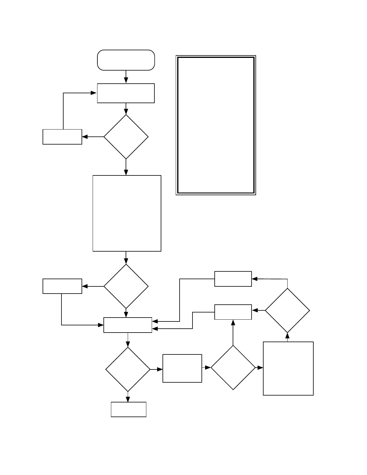
Chart 12. 02/81, DSP ROM Checksum Failure
At radio power up,
verify U404
A14, A15, A16
transisiton to a high
logic state. Verify
activity(transitions
from high to low)
on U404 - CE*.
Use ohmmeter to
electrically verify
following signal
connections to source IC:
Signal @ U404 Source
D0-D7 U405
A0-A13,A17 U405
A14-A16 U406
EPS* U406
WR*,RD* U405
VCC +5V
VSS GND
Replace U404
ADSIC
Good?
Replace U406
No
Yes
DSP ROM
ReFLASH
passed?
End
No
Yes
Repair opens.
Fail 02/81
DSP ROM Checksum
Failure
Visually inspect all
leads to U404 with
a 5x glass.
Connections
good?
No
Yes
Connections
good?
Repair opens.
Yes
No
Go to section
on ADSIC
Checksum
Failure (02/A0).
Chart C.11
ADSIC
Good?
Yes
MAEPF-26026-O
ReFLASH DSP
ROM
No
Synopsis
This failure indicates the DSP
ROM program code is incorrect.
It is implied that the DSP found
and executed enough valid code
at power up to get to the point
of verifying the rest. Basic
failure modes are as follows:
1) The contents of U404 has
been corrupted.
2) The decoding logic comprised
of U405 and U406 is not
working properly due possibly
to circuit opens or shorts or
that a failure of one or more of
these ICs has occurred.
3) U405 has failed.
Due to the fact that the DSP
successfully initialized, a
failure in one of the ICs is not
likely.
 Loading...


