8-13
Housing Assembly
Replacement
When replacing an old housing assembly, which has a housing part
number in either the 1505578Z or 1505350Z family of part numbers,
with a new housing assembly, which has a housing part number in the
1585920C family, the universal controls flex bracket may need to be
replaced (see Figures 8-1 and 8-2). Housing part numbers are molded
on the inside of the housing. A new universal controls flex bracket
(complete with bracket, liners, adhesive and aligning tool) is supplied
with the housing assemblies that have a housing part number in the
1585920C family.
For housing assembly replacement, follow the steps for disassembling
the controls seal, as described earlier in this chapter. DO NOT REMOVE
the dust cover on the new housing assembly until you have fully read
and completed the following instructions. Once the controls flex is
removed, DO NOT DISCARD.
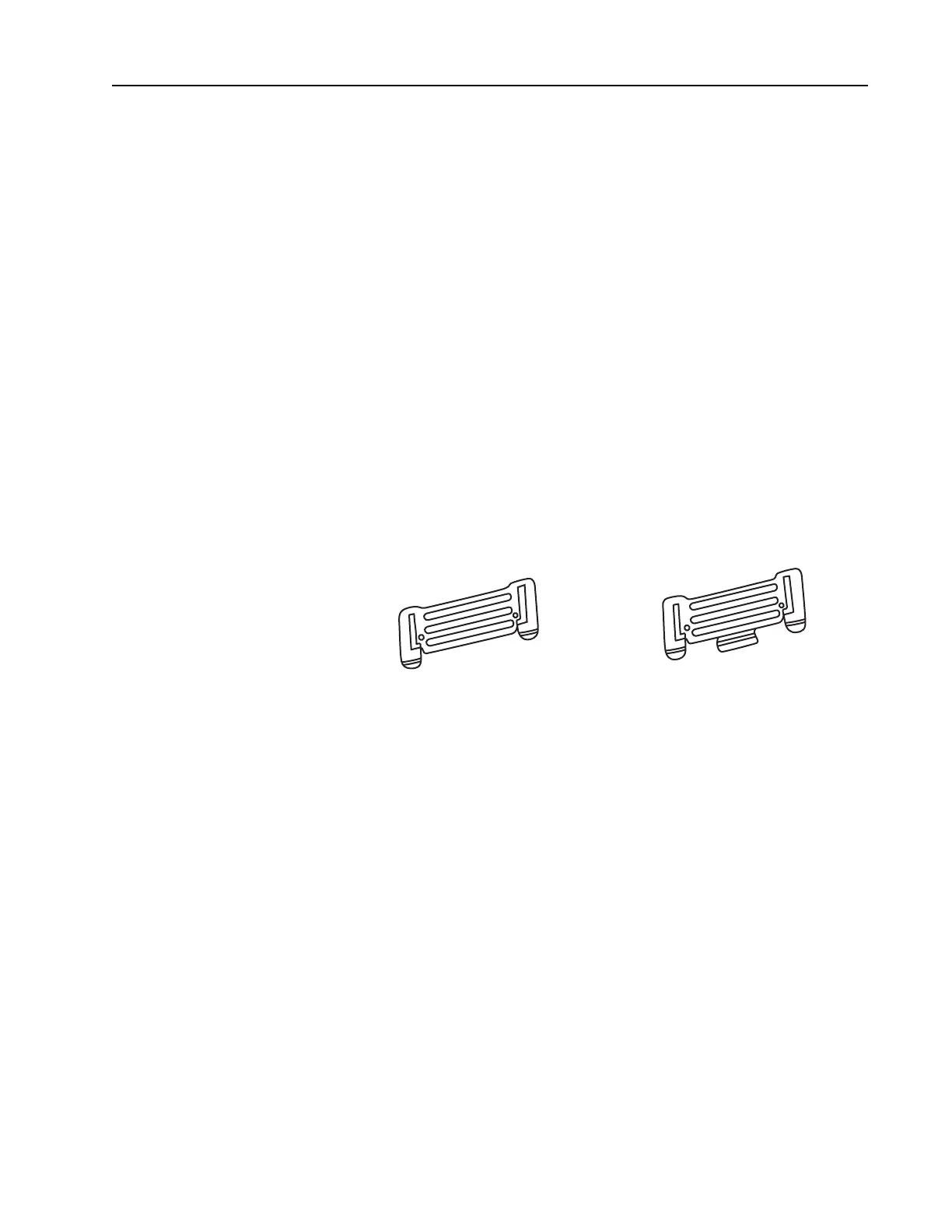
Inspect the universal connector bracket. If the current bracket
resembles the bracket shown on the left in Figure 8-17 below, you
MUST replace this bracket for the one shown on the right in Figure 8-
17. Start with step #1 below. If the bracket resembles the one shown
on the right in Figure 8-17, no bracket replacement is needed. Skip to
step #11. If a new universal connector bracket is needed, use part
number 4205582Z07 (universal bracket replacement kit).
Figure 8-17 Universal Connector Bracket
1. Carefully peel the old universal bracket from the controls flex.
2. Thoroughly clean the adhesive from this area using isopropyl
alcohol.
3. Peeling the old bracket from the controls flex may cause the flex
to curl. Roll the flex in the opposite direction to flatten out as
much as possible.
4. Once the controls flex is clean, dry and flat, use the alignment
tool supplied to apply a new layer of double-sided adhesive and a
new bracket to the controls flex. To hold the alignment tool
steady, tape it to a flat work area.
5. Refer to Figure 8-18.
 Loading...


