6-13
Most of the signals are extensions of circuits described in other areas
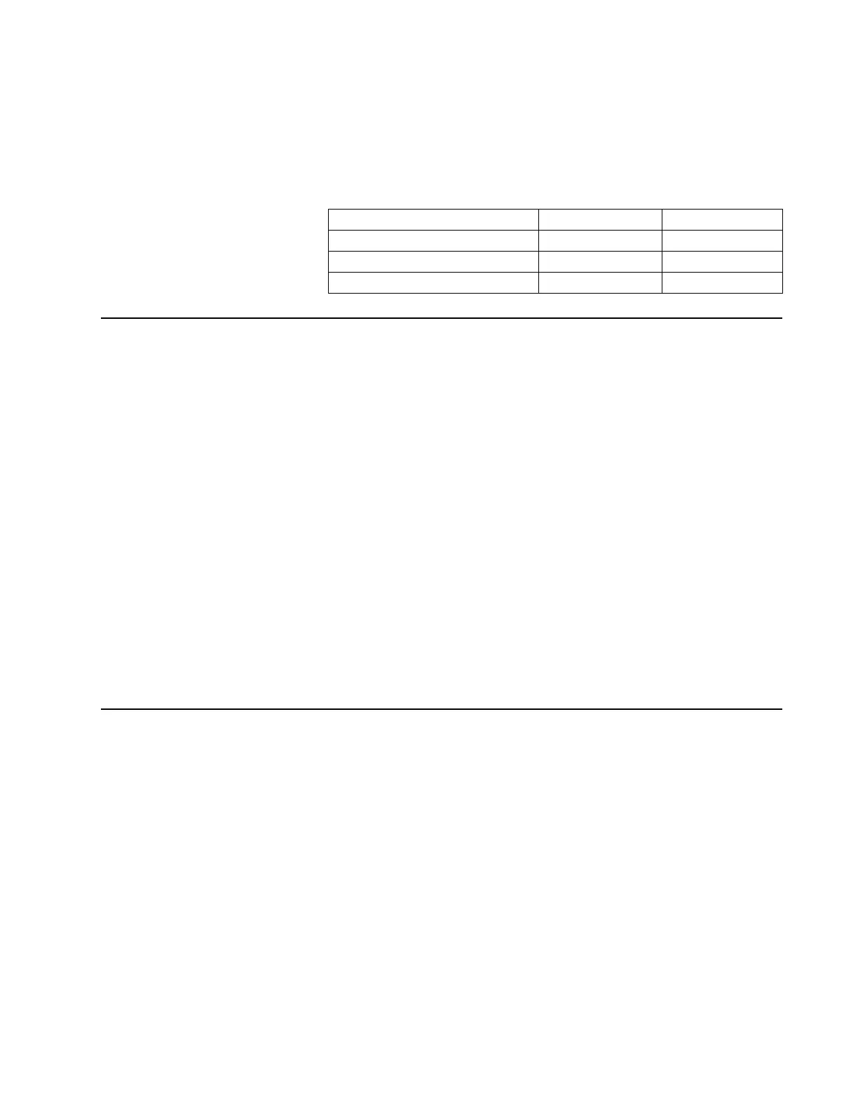
of this manual. However, there are two option select pins used to
configure special modes: Option Select 1 and Option Select 2. These
pins are controlled by accessories connected to the universal
connector. Table 6-1 outlines their functions as defined at the
universal connector.
Keypad and Display
Module
An optional integral four-line by 12-character LCD display module is
available with either a 3 x 2 keypad (model II radios) or 3 x 6 keypad
(model III radios). This unit is not considered field repairable. The
display module is connected to the controller through flex connector
P301.
The display is controlled by the MCU, which programs the display
through the SPI bus and DISP_EN* (select) line. In addition, display
backlighting is provided by two white LEDs controlled by the BL_EN
signal. Digital +5V, routed to the display, is used to power these LEDs,
as well as all other circuitry on the display.
The keypad module is connected to the controller through flex
connector P107. The keypad is read though a row and column matrix
made up of ROW1, ROW2, ROW3, ROW4, ROW5, ROW6, and COL1,
COL2, and COL3. These signals are input to I/O ports on the SLIC
(U702) and individually pulled to a high state through resistors. When
a key is pressed, the respective signals for a single row and a single
column are set to logic zero. The MCU reads these ports through the
SLIC parallel registers, provides for key debounce, and determines
which key has been pressed.
Controls and
Control Top Flex
The housing assembly top controls include an on/off switch/volume
control (S1), a 16-position mode-select switch with programmable
two-position concentric switch (U1), a programmable three-position
(A,B,C) toggle switch (S2), and a programmable top (orange) button
(SW3). The side controls include three programmable, momentary,
push button switches (side button 1 [SB2], side button 2 [SB3], and
top side button [SB1]) and a PTT switch (SW2). These components
are connected through a flex circuit to the controller at J101 (see
Figure 6-14). The assembly also contains the radio’s internal speaker
and internal microphone.
UNSW_B+ is routed through switch S1 to provide the B+_SENSE signal
which provides radio power control. Refer to “Radio Power” on page 3-1
for further details.
Table 6-1 Option Select Functions
Option Select 1 Option Select 2
External PTT 0 0
No Function (Normal) 1 1
External Speaker 0 1
 Loading...


