10-15
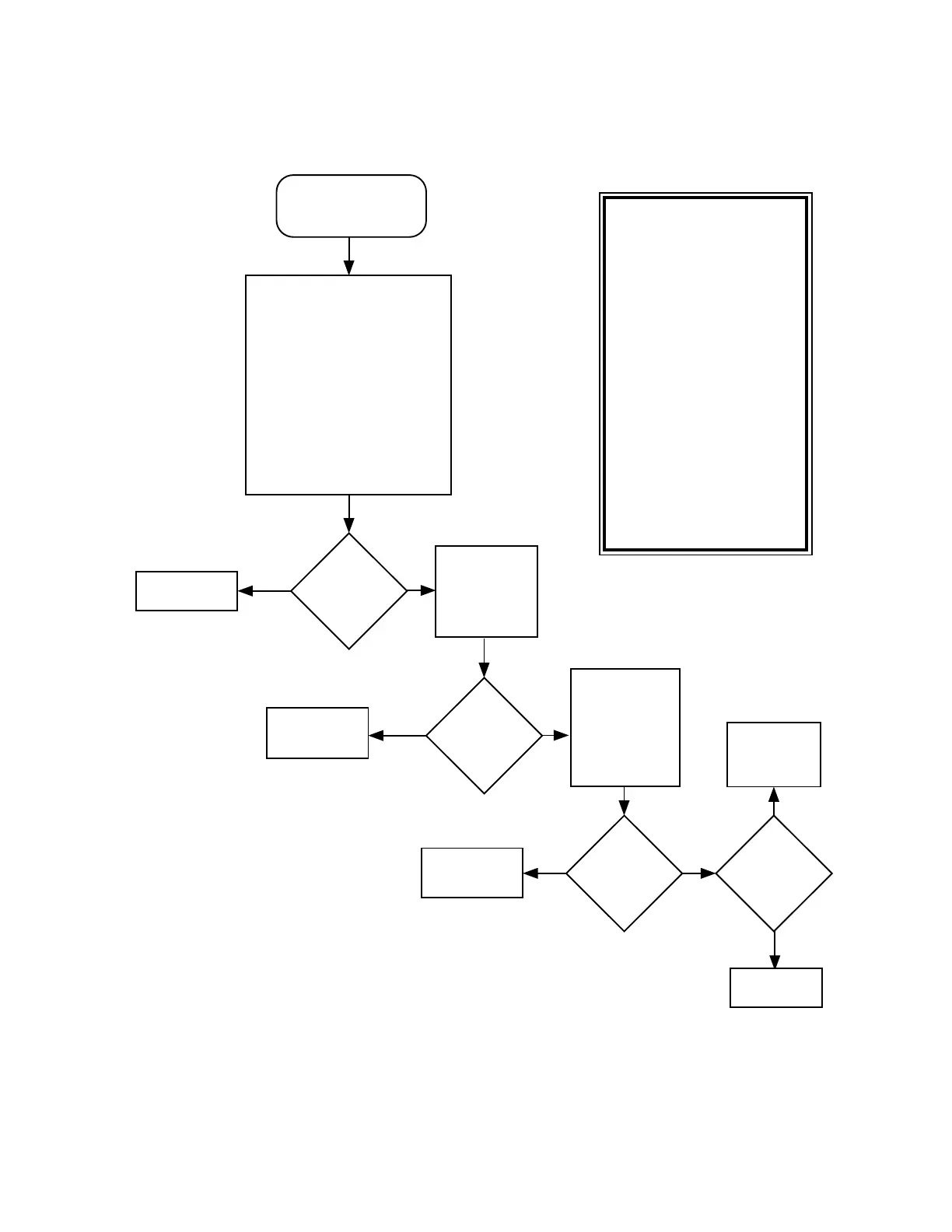
Chart 13. 02/88, DSP External SRAM Failure U414
A15 (CE*)
appears
functional?
Yes
Replace
questionable
IC (U401, U402,
or U403).
Are all
address and
data lines for all
three IC s toggling
between
0 and 5V?
Replace U405.
Yes
MAEPF-26027-O
No
No
ADSIC
checksum
error?
Refer to
section on
FAIL 02/A0.
Chart C.11
Yes
No
During and
after power up
verify U401, U402,
and U403 are
enabled by high
to low transitions of
A15, RD*, WR*.
Replace U405.
Synopsis
On power-up the DSP writes
data to the device and then
verifies the data. This failure
indicates the DSP SRAM failed
this pattern/checksum test.
U401, U402, and U403 are
selected by the DSP (U405)
address bus with address line A15.
Basic failure modes
are as follows:
1) Some problem exists
(open/shorts) with the
external address/data bus.
2) Possible failure of the DSP
address/data bus or
RD*/WR*/PS* signals
used in selecting this part.
3) Open in supply or ground to
one of the ICs.
4) Failure of one of the ICs.
Fail 02/88
DSP SRAM
U401, U402, or U403
Failure
Use ohmmeter to
electrically verify
following signal connections
to source IC:
Signal @ U401,U402,U403 Source
D0-D7 U401
D8-D15 U402
D16,D-23
D0-D23
A0-A15
WR*,RD*
U403
U405
U405
U405
VCC +5V
VSS GND
Connections
good?
Repair opens.
Yes
No
Check for
ADSIC
programming
checksum
error.
 Loading...


