6-17
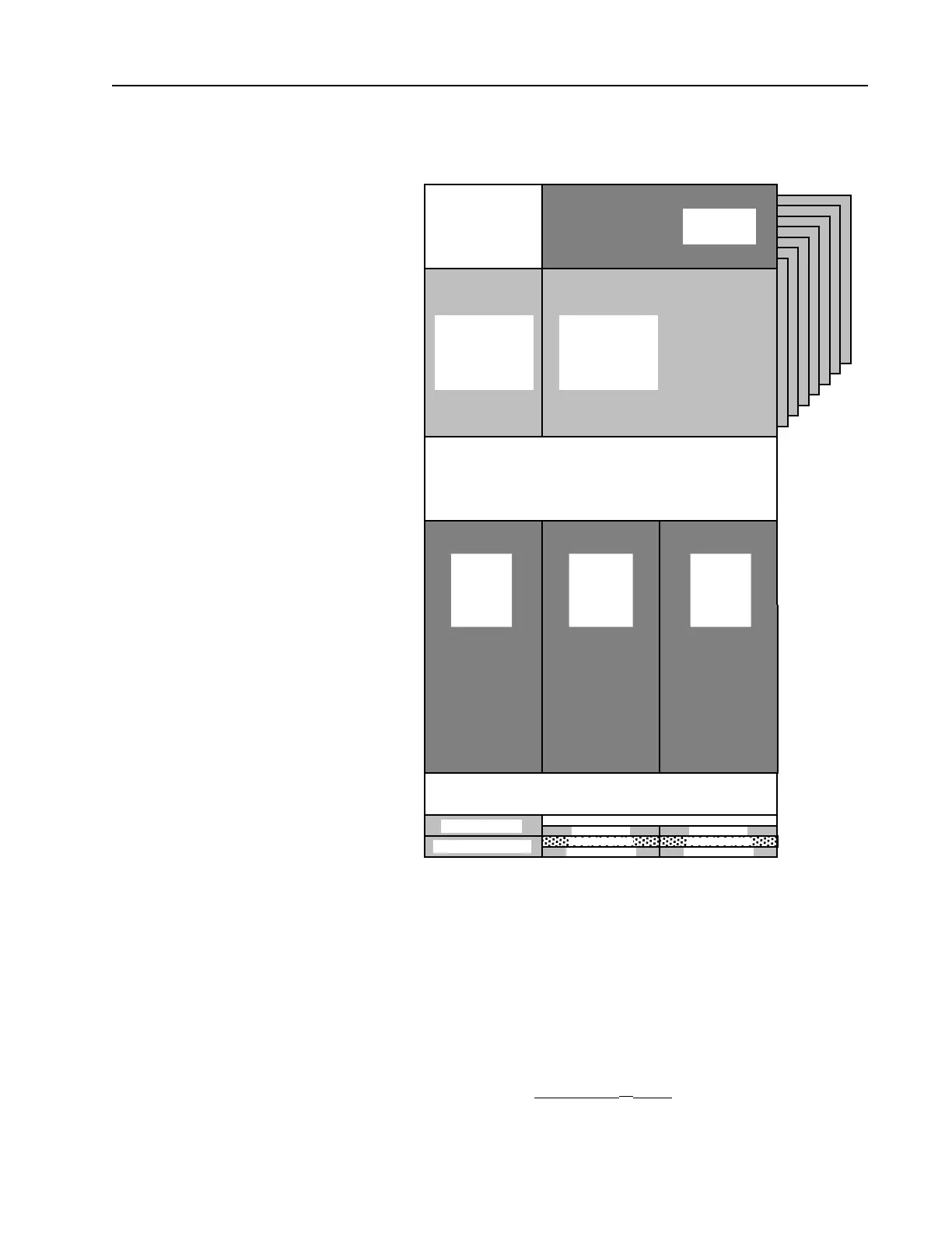
Vocoder Memory
Map
The vocoder (DSP) external bus consists of three 32k x 8 SRAMs (U401,
U402, and U403), one 256k x 8 FLASH ROM (U404), and ADSIC
(U406) configuration registers. Refer to Figure 6-16.
The DSP56001A (U405) has a 24 bit wide data bus (D0-D23) and a 16
bit wide address bus (A0 - A15). The DSP can address three 64k x 24
memory spaces: P (Program), Dx (Data X), and Dy (Data Y). These
additional RAM spaces are decoded using PS* (Program Strobe), DS*
(Data Strobe), and X/Y*. RD* and WR* are separate read and write
strobes.
The ADSIC provides memory decoding for the FLASH ROM (U404).
EPS* provides the logic A15 x (A14
⊕ A13) and is used as a select for
the ROM. The ADSIC provide three bank lines for selecting 16k byte
$0000
$01FF
$0FFF
$0200
$1000
$1FFF
$E000
$DFFF
External
RAM
U403
$2000
$7FFF
$FFFF
External
RAM
U402
$8000
DyDxP
ADS Vectors
ADSIC
Registers
$9FFF
$A000
External ROM
16KB Physical
Banks
$00000-1FFFF
Internal P Ram
ADS P Ram
Not Used
External ROM
16KB Physical
Banks
$20000-3FFFF
Internal X Rom
Internal Y Rom
MAEPF-26007-A
Internal Dx Ram
ADS Dx Ram
Internal Dy Ram
ADS Dy Ram
External
RAM
U401
Figure 6-16 Vocoder Memory Mapping
 Loading...


