10-9
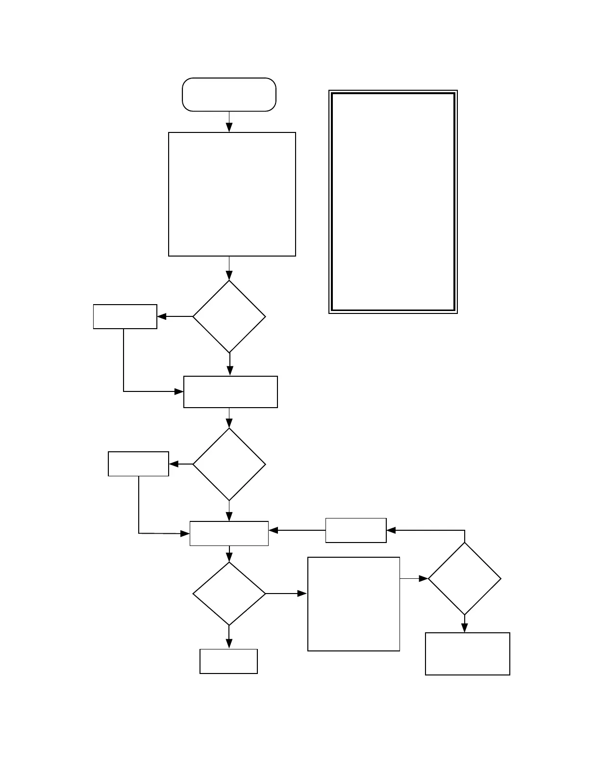
Chart 7. 01/82 or 002, External EEPROM Checksum Failure
Reprogram
external EEPROM.
External
EEPROM
reprogrammed?
End
Yes
Repair opens.
Connections
good?
No
Yes
Verify operation of
Power-Down Reset Per
Fig. W9.
Reset
Functional?
Replace U726.
No
Yes
Fail 01/82 or 002
External EEPROM
Checksum Failure
Use ohmmeter to electrically
verify following signal
connections to source IC:
Signal @ U706 Source
HD0-HD7 U701
HA0-HA13 U701
HA14OUT U702
EE1CS* U702
OE*,MEMR/W* U702
RESET* U726
VCC +5V
VSS GND
Check for operation of
U701 and U702 as
follows: During radio
power up Self-Test,
verify activity
(transisitons from high
to low) on U706 -
EE1CS*, and OE*.
Replace
U706.
No
Yes
No
MAEPF-26020-O
Initial
operation
checks
Good?
Refer to section on
Power-up Failure C.3
and/or Fails to
Bootstrap C.4.
Synopsis
This failure indicates the
External EEPROM data
containing mostly customer
specific channel/mode
information is incorrect.
Basic failure modes are as
follows:
1) The contents of U706 has
been corrupted. A possible
cause of this failure would be
the improper operation of the
RESET circuit during a radio
power down sequence.
2) The decoding logic comprised
of U701 and U702 is not
working properly due possibly
to circuit opens or shorts or
that a failure of one or more of
these ICs has occurred.
3) U706 has failed.
 Loading...


