2205Q2JE-HO-S6-N_2020.01.
Chapter 5 Maintenance and Inspection
SCV-series Screw Compressor 5.5 Reassembly
5-40
5.5.7 Thrust Bearing Block
[160 to 250V**] [320V*D]
Note: 250V** models do not use the No.41.
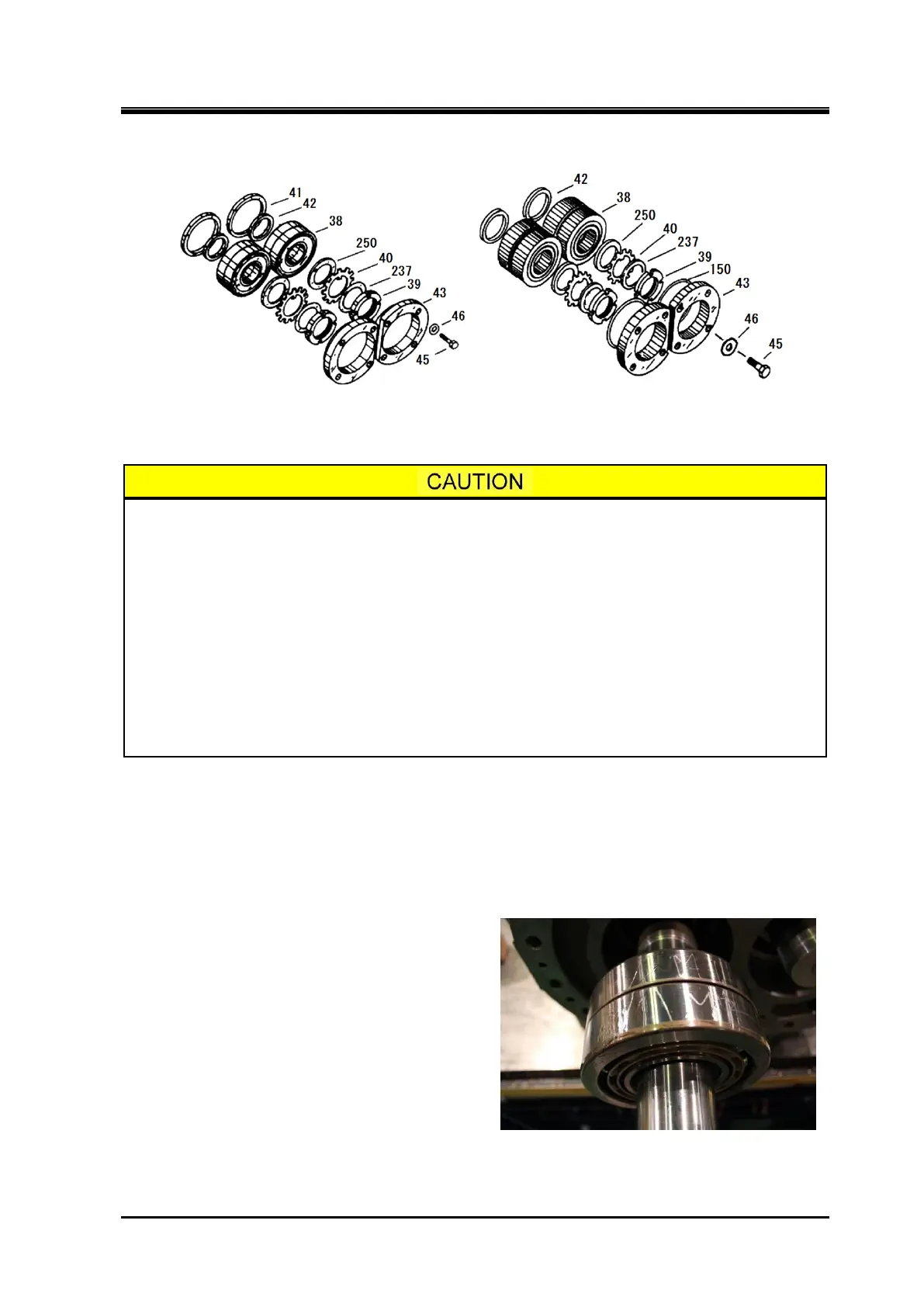
Figure 5-15 Exploded View of the Thrust Bearing Block
The torsional slip washer [237] and lock washer [39] must be replaced with new ones.
If the removed thrust bearing is to be installed as it is, check the marking of "M" or
"F" on the thrust bearing outer race spacer [41] (160V**, 200V** models) and
alignment spacer [42], and assemble them in the same combinations as they ware
disassembled. This is important in controlling the end clearance on the discharge
side of the rotor.
Even if the same bearing is installed, the work must be very carefully done as the
dimension can change if any foreign matter such as a chip of paint or dust is pinched
by the thrust bearing outer race spacer and/or alignment spacer.
In determining the installation direction of the thrust bearing, there are two methods
depending on the existence of an alignment "V" marking on the outer circumference
of the bearing. Install the bearing according to the following procedure provided for
each case.
The assembly sequence for this part is as illustrated in Figure 5-15. The important points to be noted in
the procedure are described below:
a) Check the marking of either "M" or "F" on the thrust bearing outer race spacer and alignment spacer
to ensure that the units are assembled in the same combination of parts.
The front and back of the outer race spacer and alignment spacer must be distinguished when it is
installed. The larger chamfering side is on the machine side, and the smaller chamfering side is on
the thrust bearing side.
b) If thrust bearing has a "V" marking on the outer
circumference, it means that the installation
direction of the bearing will sensitively affect the
end clearance adjustment. In this case, the
bearing must be installed with the pointed end of
the marking pointed toward the inside of the
machine.
If there is no "V" marking, it means that the
direction of the bearing installation will not affect
the end clearance adjustment. However, in order
to clearly determine the orientation (whether it is
on the inside or outside of the machine), first
combine both bearings with the bearing number carving facing the outside of the machine. Then,
use a blue whetstone to write the above "V" marking on the bearing to show the inside direction of
the machine (see above picture). Then, install the bearing

 Loading...
