2205Q2JE-HO-S6-N_2020.01.
Chapter 5 Maintenance and Inspection
SCV-series Screw Compressor 5.4 Disassembly and Inspection
5-23
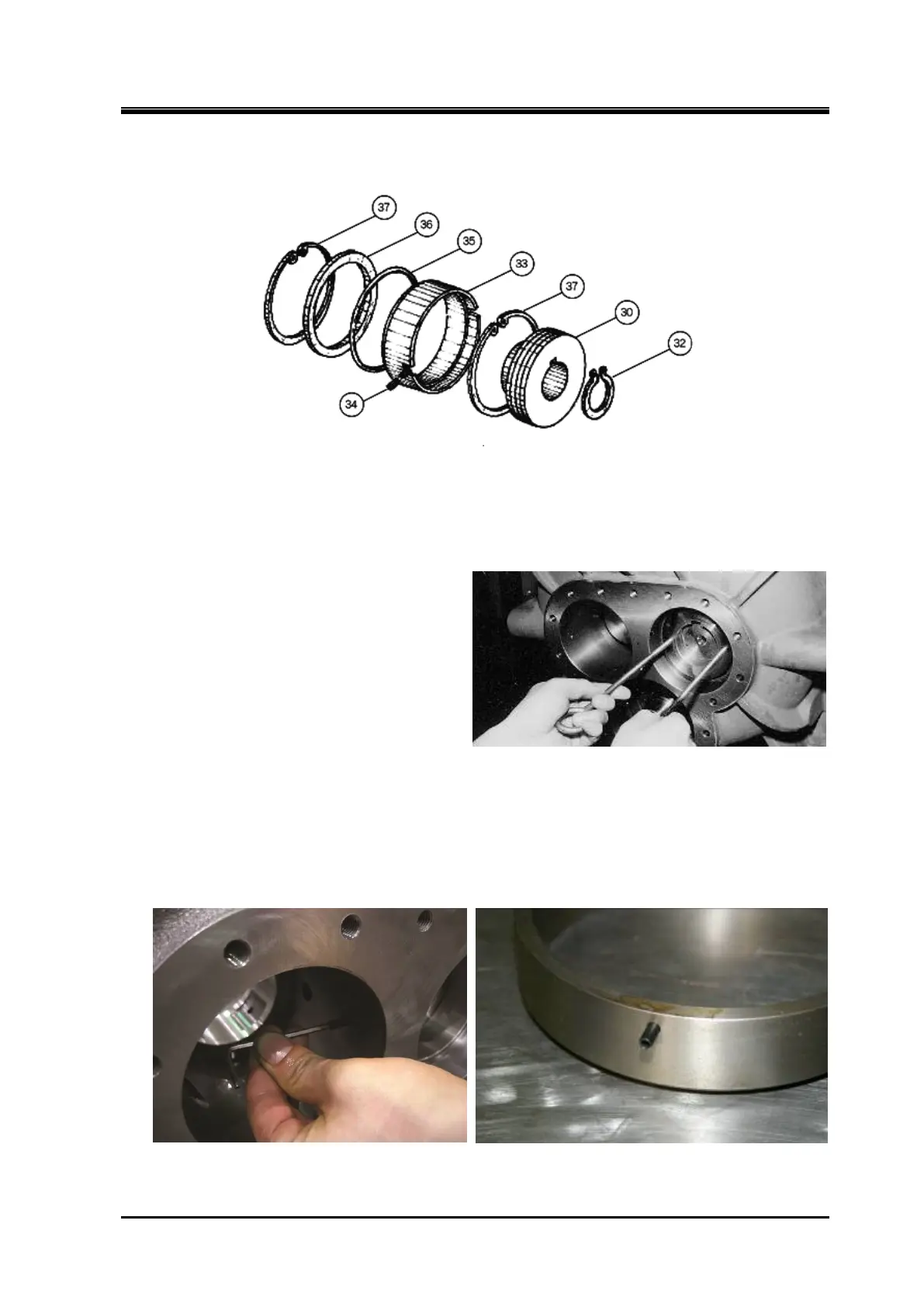
5.4.5 Balance Piston Block
Figure 5-10 Exploded View of Balance Piston Block
5.4.5.1 Disassembly
a) Remove the snap ring [32] that secures the
balance piston [30] on the M rotor shaft using
external snap ring pliers.
b) Screw in two M8 eye bolts to the hole in the
balance piston and pull out the piston in
parallel with the axis of the shaft (see right
picture). It is not necessary to remove the
balance piston key [31] embedded in the
rotor axis.
c)
The balance piston sleeve is locked by either of the following methods:
Type 1 (following picture to the left) for 160 to 250V** models:
Locked by a screw at the notch in the balance piston sleeve
Type 2 (following picture to the right) for 320V*D models:
Locked by a spring pin by driving the pin into the sleeve and fitting it into the suction cover
groove
Type 1: Locked by a Screw Type 2: Locked by a Spring Pin

 Loading...
