2205Q2JE-HO-S6-N_2020.01.
Chapter 5 Maintenance and Inspection
SCV-series Screw Compressor 5.5 Reassembly
5-48
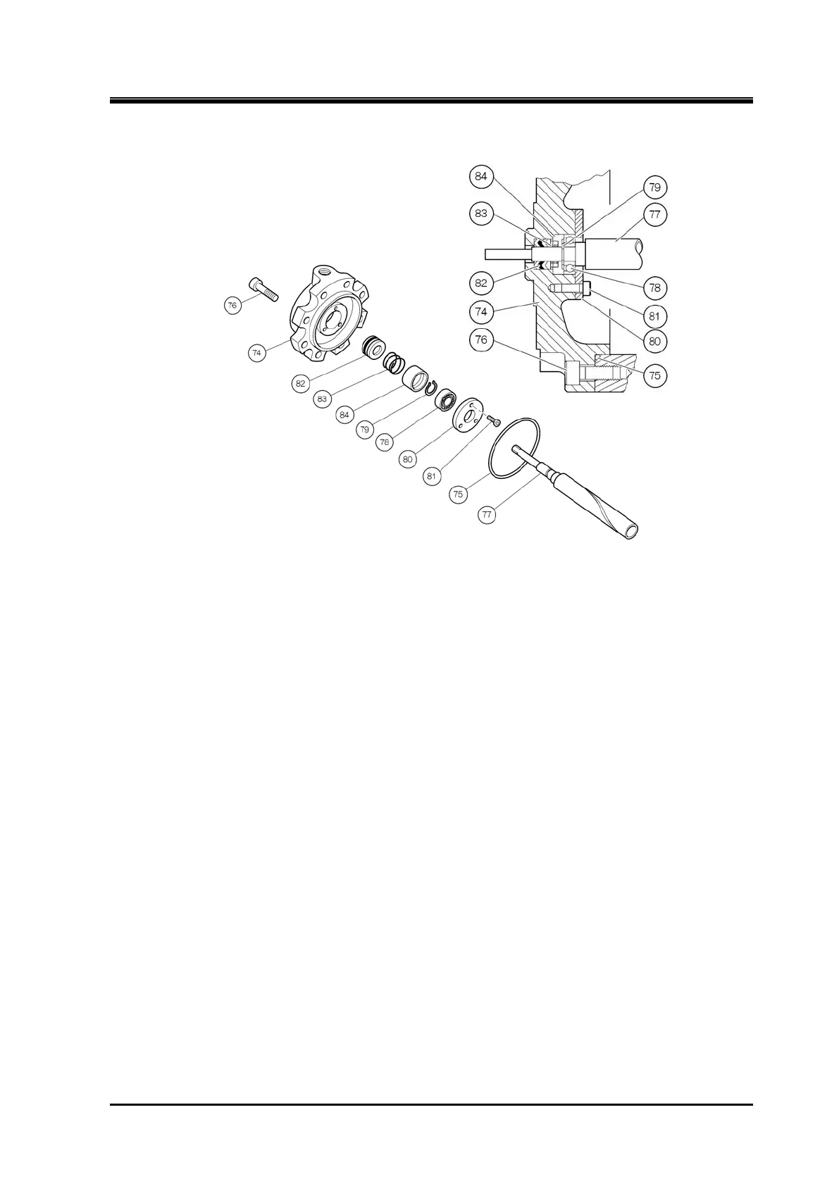
5.5.9 Unloader Cover
Figure 5-18 Unloader Cover Block
a) Use eye bolts to move the unloader piston back and forth to check the normal operation again.
b) Assemble the ball bearing [78] on the shaft portion of the indicator cam [77]. When fitting the
bearing onto the shaft, push the inner race of the bearing. Pushing the outer race may damage the
bearing. Push the bearing to the stepped portion of the indicator cam and retain the bearing with the
external snap ring [79].
c) Sufficiently apply oil on the unloader cover [74], and install the V-ring set [82] in it. One of the rings
of the V-ring set (i.e., dark colored one) is made of rubber to improve the sealing performance, and
is placed as the second item from the outside as shown in Figure 5-18.
The orientation of the V-ring must be such that the apex of the V-shape faces the outside and the
lips face inside.
d) Install the spring [83] and the spring retainer [84] into position. Then, insert the shaft of the indicator
cam assembled in Step b) above into the V-ring. Lastly, fasten the bearing gland [80] onto the
unloader cover to retain the bearing.
e) After making sure that the indicator cam rotates smoothly, attach the O-ring [75] to the unloader
cover.
f) Install the unloader cover on the unloader cylinder [60]. Making sure that the guide pin [68] of the
unloader push rod [67] is well engaged in the spiral groove of the indicator cam, push-in the
unloader cover.
With the oil supply hole for the unloader operation up, secure the unloader cover by fastening the
hexagon socket head cap screws [76] at the specified torque.

 Loading...
