2205Q2JE-HO-S6-N_2020.01.
Chapter 5 Maintenance and Inspection
SCV-series Screw Compressor 5.4 Disassembly and Inspection
5-27
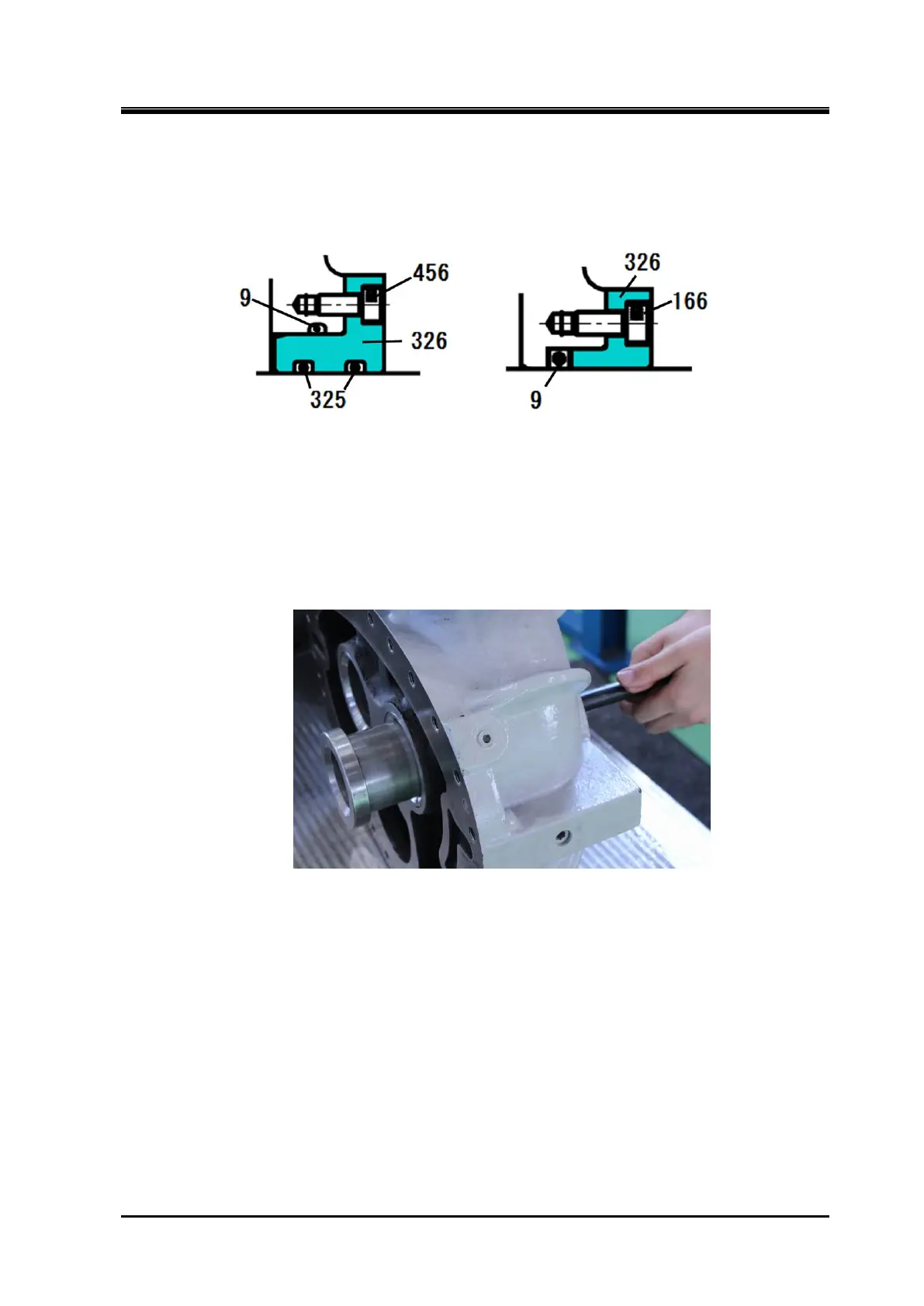
f) The O-ring and O-ring gland [326] are mounted in the unloader push rod passes part of the suction
cover. Remove them. At this time, take care not to lose the four fastening screws for O-ring gland
due to their smallness (M5). The structure and part No. of around the O-ring gland are slightly
different between 320V*D models and other models as shown in Figure 5-11.
[160 to 250 V**] [320V*D]
Figure 5-11 Difference around the O-ring gland
g)
The side bearing [28] has been press fit from the balance piston cover side of the suction cover.
Remove the snap ring [29] using internal snap ring pliers.
h)
Either push out the side bearing from the rotor casing side using some block or pull it out using a
special tool such as shown in following picture.
5.4.7.2 Inspection
a) Check the oil inlet path to the balance piston part of the suction cover by spraying air, etc.
b)
We recommend unconditional exchange of the side bearings on the occasion of the compressor
overhaul, but for confirmation of the compressor condition and system operating condition, carefully
check the sliding part metal surface of the side bearings.
If the metal surface is gray or any foreign matter is buried, also carefully check the wear of the rotor
shaft.
c) The inside surface of the rotor casing should have no problems because sufficient clearance is
provided. However, if any trace of scraping by the end of the rotor is found, it should be determined
that the thrust bearing is defective.
It is also necessary to check the operational condition, such as whether the system is operated for a
long time with a high intermediate pressure.

 Loading...
