2205Q2JE-HO-S6-N_2020.01.
Chapter 5 Maintenance and Inspection
SCV-series Screw Compressor 5.5 Reassembly
5-49
5.5.10 Bearing Cover
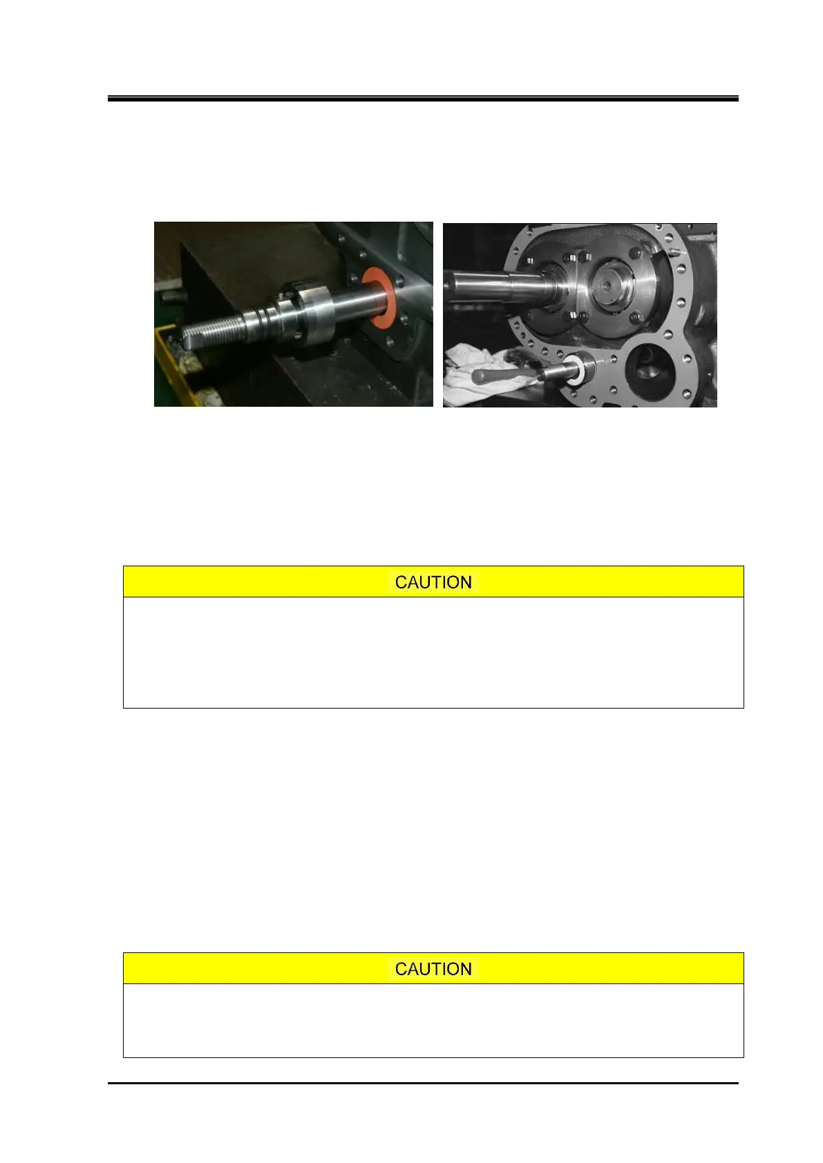
a) Install the thrust washer [449], as shown a red arrow in following picture to the left, on the Vi
adjusting rod. In case of 320V*D models except other models are installed the Vi adjusting rod
retainer [600] as shown in following picture to the right.
b) Before installing the bearing cover [16], check that the claw of the lock washer of the thrust bearing
block have been properly bent to prevent rotation and that the hexagon head bolts fastening the
thrust bearing gland are with conical spring washers.
c) For ensuring the safety, screw two stud bolts in the upper bolt holes on the flange of the bearing
head [11].
d) After applying sufficient amount of oil, etc. on the flange surface of the bearing head as well as on
both sides of the gasket [17] for the bearing cover, attach the gasket onto the flange surface, and
retain the gasket by hanging at the upper stud bolts.
The bearing cover gasket is not symmetric because there is a hole for lubricating
oil line to the mechanical seal block in the left (seal) side.
Be careful that do not mistake the direction of the gasket when attaching onto the
bearing head flange surface. Mistaken the direction of the gasket causes the
lubrication failure to the mechanical seal block.
e) In case of 160V** and 200V** models, holding the bearing cover by your hand and install it on the
bearing head. Sideways discharge type compressors have uneven balance so care must be taken
when working on them.
For the 250V* and 320V*D models, the bearing cover has a threaded hole for installing a eye bolt in
its center-of-gravity position. Screw an eye bolt into this threaded hole, and lift up and install the
bearing cover to the bearing head. At this time, while keeping the clearance between the two
components’ peripheries, make sure not to damage the M rotor’s installation area of the Mechanical
seal assembly.
f) After correctly setting the position of the alignment pins, lightly tap the flange at different places
alternately using a copper hammer or soft hammer to install the cover in position.
g) When the cover has come to the position the bolts can be screwed in, screw in two or three
hexagon socket head cap screws and evenly tighten them to reduce the clearance and make the
cover contact the bearing head. Then, tighten all the bolts at the specified torque.
Since fastening bolts for the bearing cover are used two or three kinds of bolt
lengths depending on the models and fitting positions, make sure to confirm the
bolt differences in your assembly work of this block.

 Loading...
