2205Q2JE-HO-S6-N_2020.01.
Chapter 5 Maintenance and Inspection
SCV-series Screw Compressor 5.5 Reassembly
5-43
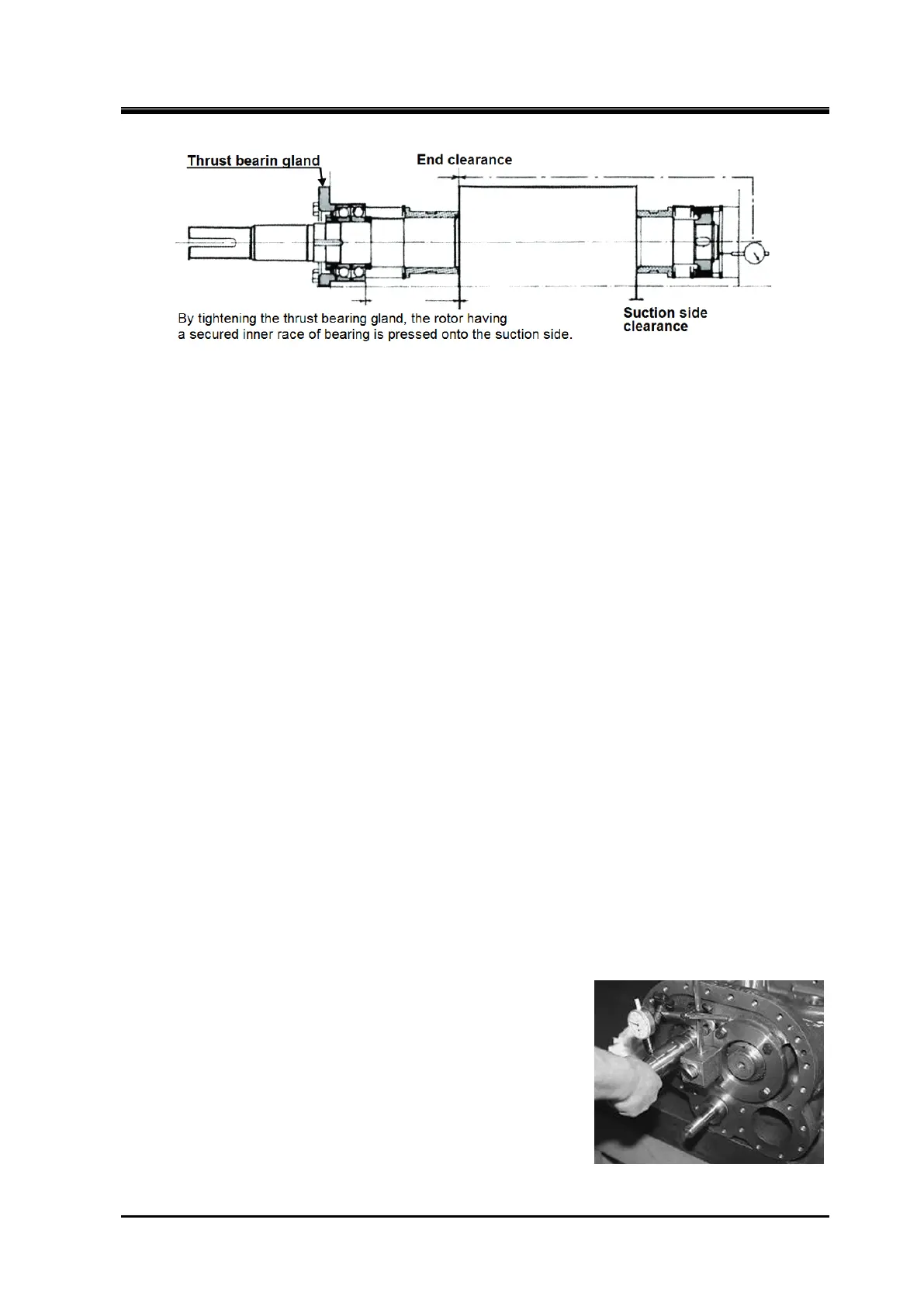
Figure 5-17 Measurement of the End Clearance
5.5.7.2 End Clearance Adjustment Procedure
(1) When the end clearance is less than the specified value
In this case, a shim (thrust adjustment liner) must be inserted between the thrust alignment
spacer [42] and the inner race of the thrust bearing to increase the end clearance.
The thickness of the shim must be determined by the difference between the specified end
clearance and the measured value.
◆ Although the thrust adjustment liner is not shown in the exploded view, you can place an
order to us indicating the model name.
Also, in case of 160V** or 200V** models, using a highly accurate surface grinding machine or
asking professional service vendors to grind, grind the surface of thrust bearing outer race
spacer [41] by the difference from the specified value.
After grinding the flat surface, measure the whole circumference of the outer race spacer by
using a micrometer, and check that the thickness is even.
(2) When the end clearance exceeds the specified value
If any shim (thrust adjustment liner) has been inserted between the thrust bearing alignment
spacer and the inner race of the thrust bearing, and the thickness corresponds to the difference
between the measured end clearance and the specified value, just remove the shim.
If no shim is used or the thickness of the shim is insufficient to compensate for the excess end
clearance, use a surface-grinding machine (or ask a vendor) to make the thrust bearing
alignment spacer [42] thinner by the amount of the end clearance difference between the
measured and specified values. After the surface grinding is done, use a micrometer to measure
the thickness of the spacer for the entire circumference to make sure the thickness is even.
(3) Measuring the run-out of the rotor shaft
If the end clearance adjustment has been successfully completed, then measure the run-out of
the l M rotor shaft using a dial gauge at the point of the mechanical seal attachment and turning
the shaft by hand (see following picture).
A run-out of up to 0.03 mm is acceptable for all models. The run-out occurs if the thickness of the
thrust alignment spacer is not even or the marking on the
thrust bearing is not properly positioned. And it occurs if
fastening the lock nut performed without changing the
position of the lock nut wrench, . The run-out also becomes
significant if any small foreign matter is present in between
relevant parts.
If the run-out exceeds the allowable value, disassemble this
block again even if the end clearance is within the specified
limits, and adjust the relative position of the outer race
spacer, alignment spacer and thrust bearing.
This adjustment is very important as any run-out affects the
function and service life of the mechanical seal.

 Loading...
