2205Q2JE-HO-S6-N_2020.01.
Chapter 5 Maintenance and Inspection
SCV-series Screw Compressor 5.4 Disassembly and Inspection
5-21
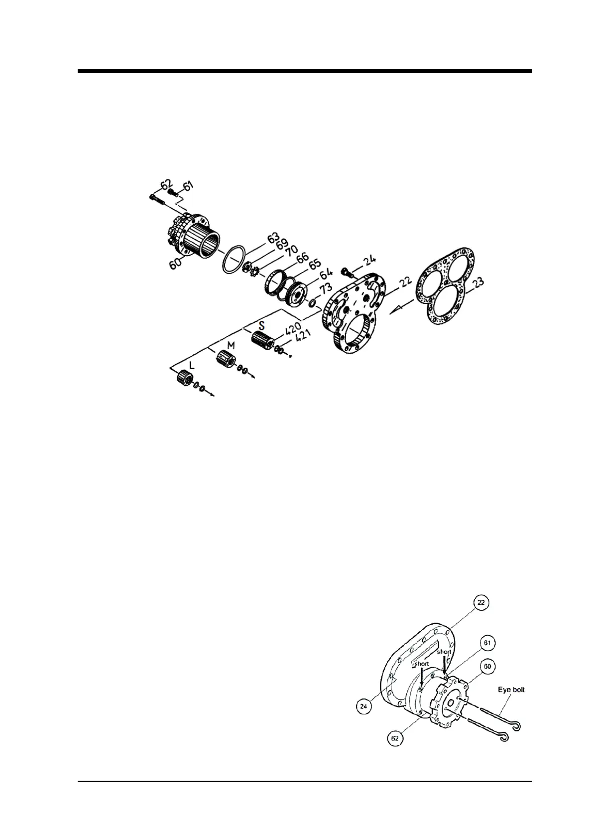
5.4.4 Unloader Cylinder and Balance Piston Cover
Inside the unloader cylinder [60] is an unloader piston [64] around which the cap seal [66] and O-ring
[65] are fitted. The unloader piston is assembled to the unloader push rod [67], which operates the
unloader slide valve, with the lock nut [69].
Unloader cylinder is secured to the balance piston cover [22] with two short hexagon head cap screws
61] and to the suction cover with six log hexagon head cap screws [62].
Figure 5-7 Unloader Cylinder Block and Balance Piston Cover (Example: 320V*D)
5.4.4.1 Disassembly
a) Remove the cap nut [522] on the bearing head side of the Vi adjusting rod [444], loosen the hexagon
nut [453], and set the variable Vi auxiliary slide valve to the L port position (by turning the Vi
adjusting rod counterclockwise until it stops).
b)
Screw the eye bolts into the two screw holes in the unloader piston [64] to move the piston toward
the indicator to the full-load position.
c)
Unbend the claws of the lock washer [70] on the lock nut [69] that is securing the piston to the push
rod [67].
d)
Loosen the lock nut using the lock nut wrench. Remove the unloader piston from the push rod using
the eye bolts again.
e) Remove the balance piston cover [22] fastening bolts
(hexagon head cap screws) [24] and the hexagon
head cap screws [62] fastening the unloader cylinder
[60] to suction cover.
After that, pull out the unloader cylinder with balance
piston cover.
At this time, as oil remains in the balance piston and
side bearing block, be careful of the oil that will flow out
when the balance piston cover is removed.
Figure 5-8 Removing the Unloader Piston

 Loading...
