2205Q2JE-HO-S6-N_2020.01.
Chapter 5 Maintenance and Inspection
SCV-series Screw Compressor 5.4 Disassembly and Inspection
5-17
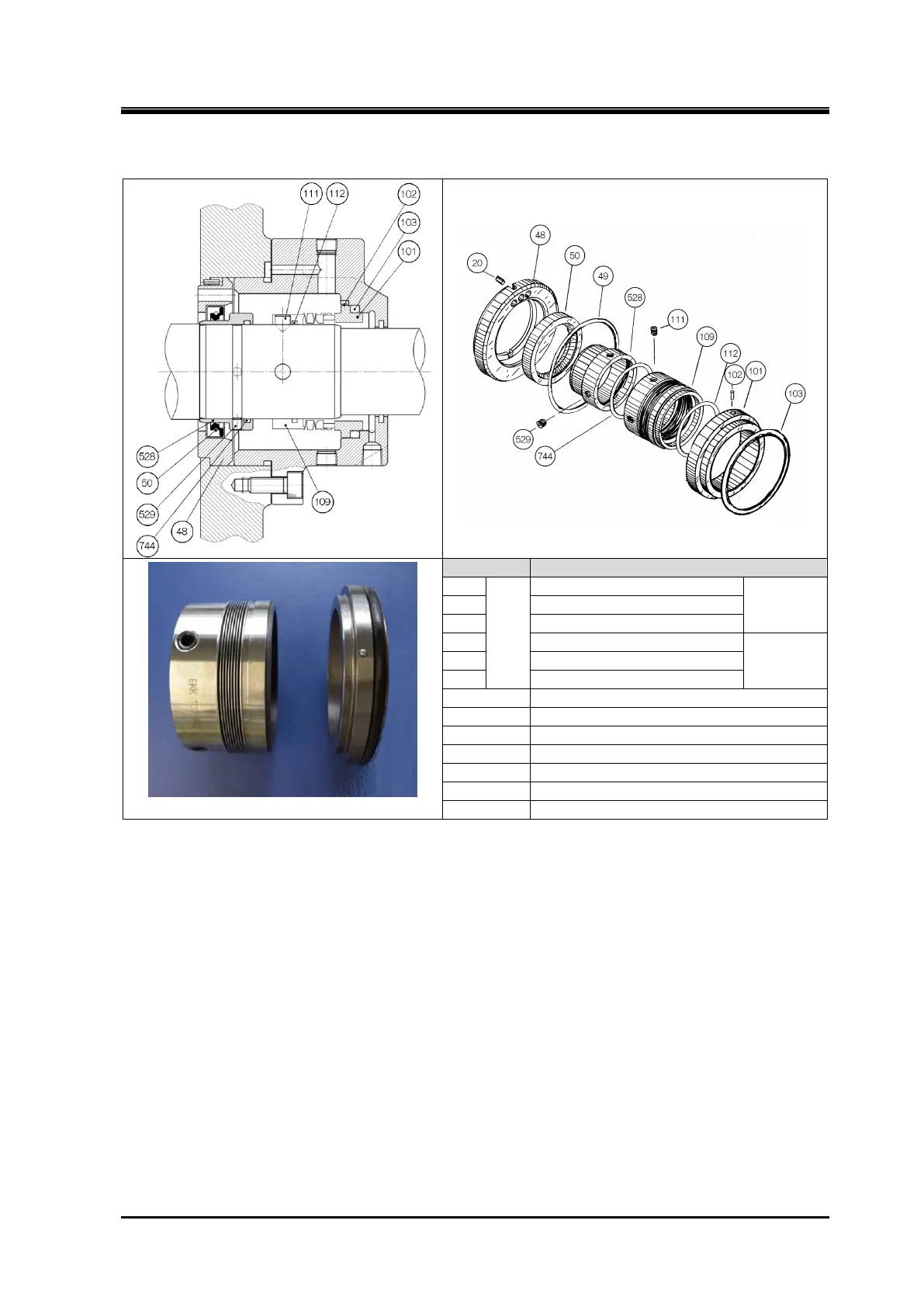
5.4.2 Shaft Seal Block
Mechanical Seal assembly
100
Stationary
rings
Rotating
rings
Set screw for oil seal sleeve
Note: [528], [529], [744] are not used to 160V** models.
Figure 5-5 Details of BBSE-type Mechanical Seal Assembly and Related Parts
5.4.2.1 Disassembly
a) Of the eight hexagon socket head cap screws [53] securing the seal cover [51], remove six bolts
leaving two diagonally opposite bolts.
b) Loosen the remaining two screws alternately and evenly, a little at a time. When the screws are
loosened to some extent, the seal cover will be pushed by the spring force of the seal to create a
gap under the cover. The gap will not be created if the gasket is sticking to both surfaces. In this
case, free the cover by screwing M8 eye bolts into the jacking screw threads on the seal cover to
separate it.
c) As the oil inside will flow out through the gap, be ready to receive the oil with a container.
d) Pull out the seal cover in the direction of the rotor shaft axis. Inside the cover, there is the mating
ring fitted with the O-ring. In this, carefully remove the seal cover for the mating ring not to be
damaged by touching the shaft.
e) Remove the O-ring [49] between the seal cover and oil seal retainer [48].

 Loading...
