EasyManuals Logo
Home>mycom>Air Compressor>SCV Series

mycom SCV Series User Manual

mycom SCV Series
161 pages
To Next Page IconTo Next Page
To Previous Page IconTo Previous Page
Page #116 background imageLoading...
Page #116 background image
2205Q2JE-HO-S6-N_2020.01.
Chapter 5 Maintenance and Inspection
SCV-series Screw Compressor 5.5 Reassembly
5-55
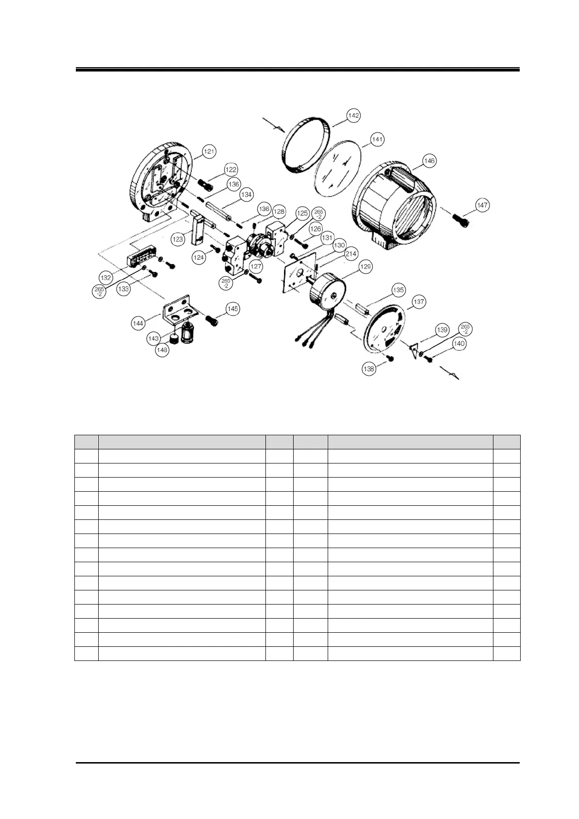
Figure 5-20 Exploded View of the Unloader Indicator (Traditional standard type)
Table 5-13 Component Parts of the Unloader Indicator (Traditional standard type)
P/N
Part Name
Q'ty
P/N
Part Name
Q'ty
121
Micro-switch base plate
1
136
Hexagon socket set screw, M3×14
3
122
Hexagon socket head cap screw, M6×20
3
137
Dial, SCV
1
123
Micro-switch base plate
1
138
Phillips Screw, M3×5
2
124
Phillips Screw, M3×10
2
139
Indicator needle
1
125
Micro-switch
2
140
Phillips Screw, M3×10
1
126
Phillips Screw, M3×25
4
141
Indicator glass
1
127
Micro-switch cam, 0 to 100%
1
142
Indicator glass spacer
1
128
Hexagon socket set screw, M4×8
1
143
Electric cable gland
1
129
Potentiometer
1
144
Bracket
1
130
Potentiometer mounting plate
1
145
Hexagon socket head cap screw, M6×15
2
131
Phillips Screw, M3×5
3
146
Unloader indicator cover
1
132
Terminal block
1
147
Hexagon socket head cap screw, M6×15
3
133
Phillips Screw, M3×20
2
148
Plug
1
134
Dial plate support [2]
2
214
Spring pin 2 dia. ×8
1
135
Dial plate support [1]
2
265-2
Spring washer, M3
7

Table of Contents

Questions and Answers:

Question and Answer IconNeed help?

Do you have a question about the mycom SCV Series and is the answer not in the manual?

mycom SCV Series Specifications

General IconGeneral
Brandmycom
ModelSCV Series
CategoryAir Compressor
LanguageEnglish

Related product manuals