6-4 | ni.com
Chapter 6 Digital I/O
Digital Waveform Acquisition
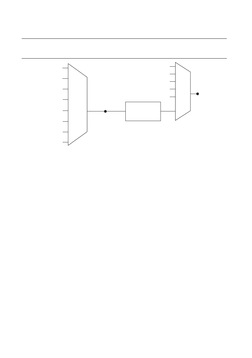
Figure 6-2 summarizes all of the timing options provided by the digital input timing engine.
Figure 6-2. Digital Input Timing Options
You can acquire digital waveforms on the Port 0 DIO lines. The DI waveform acquisition FIFO
stores the digital samples. X Series devices have a DMA controller dedicated to moving data
from the DI waveform acquisition FIFO to system memory. The DAQ device samples the DIO
lines on each rising or falling edge of a clock signal, DI Sample Clock.
You can configure each DIO line to be an output, a static input, or a digital waveform acquisition
input.
X Series devices feature the following digital input timing signals:
•
DI Sample Clock Signal
*
•
DI Sample Clock Timebase Signal
• DI Start Trigger Signal
*
•
DI Reference Trigger Signal
*
•
DI Pause Trigger Signal
*
Signals with an
*
support digital filtering. Refer to the
PFI Filters section of Chapter 8, PFI, for
more information.
DI Sample Clock Signal
The device uses the DI Sample Clock (di/SampleClock) signal to sample the Port 0 terminals
and store the result in the DI waveform acquisition FIFO.
You can specify an internal or external source for DI Sample Clock. You can also specify
whether the measurement sample begins on the rising edge or falling edge of DI Sample Clock.
Revamp AO timing options with DI timebase and clocks
PFI, RTSI
PXI_STA R
Analog Comparison
Event
20 MHz Timebase
100 kHz Timebase
PXI_CLK10
Programmable
Clock
Divider
DI Sample Clock
Timebase
PFI, RTSI
PXI_STA R
Analog Comparison Event
Ctr
n Internal Output
DI Sample Clock
100 MHz Timebase
DSTAR <A..B>
DSTAR <A..B>

 Loading...