4-26 | ni.com
Chapter 4 Analog Input
When using an externally generated AI Sample Clock, you must ensure the clock signal is
consistent with respect to the timing requirements of AI Convert Clock. Failure to do so may
result in a scan overrun and will cause an error. Refer to the
AI Convert Clock Signal section for
more information about the timing requirements between AI Convert Clock and AI Sample
Clock.
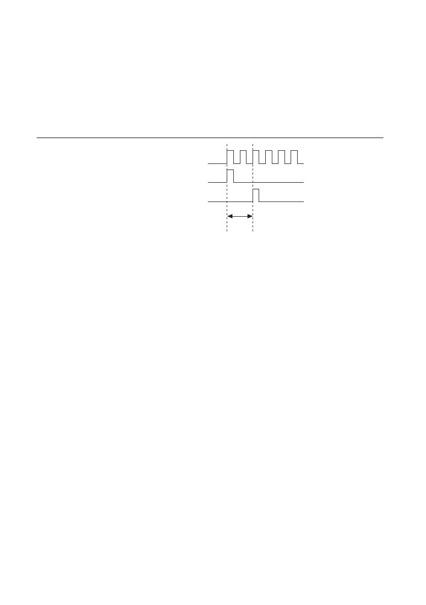
Figure 4-16 shows the relationship of AI Sample Clock to AI Start Trigger.
Figure 4-16. AI Sample Clock and AI Start Trigger
AI Sample Clock Timebase Signal
You can route any of the following signals to be the AI Sample Clock Timebase
(ai/SampleClockTimebase) signal:
• 100 MHz Timebase (default)
• 20 MHz Timebase
• 100 kHz Timebase
•PXI_CLK10
•RTSI <0..7>
• PFI <0..15>
• PXI_STAR
• PXIe_DSTAR<A,B>
• Analog Comparison Event (an analog trigger)
AI Sample Clock Timebase is not available as an output on the I/O connector. AI Sample Clock
Timebase is divided down to provide one of the possible sources for AI Sample Clock. You can
configure the polarity selection for AI Sample Clock Timebase as either rising or falling edge,
except on 100 MHz Timebase or 20 MHz Timebase.
AI Sample Clock Timebase
AI Start Trigger
AI Sample Clock
Delay
From
Start
Trigger

 Loading...