A-10 | ni.com
Appendix A Device-Specific Information
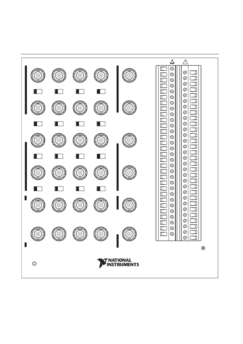
Figure A-7 shows the pinout of the NI USB-6343 BNC. For a detailed description of each signal,
refer to the
I/O Connector Signal Descriptions section of Chapter 3, Connector and LED
Information
.
Figure A-7. NI USB-6343 BNC Pinout
Refer to Table 7-9, X Series PCI Express/PXI Express/USB Mass Termination/USB BNC Device
Default NI-DAQmx Counter/Timer Pins
, for a list of the default NI-DAQmx counter/timer pins
for this device. For more information about default NI-DAQmx counter inputs, refer to
Connecting Counter Signals in the NI-DAQmx Help or the LabVIEW Help.
ANALOG INPUT
DIGITAL AND TIMING I/O
ANALOG OUTPUT
AI 0
FS GS
AI 1
FS GS
AI 2
FS GS
AI 3
FS GS
P0.8
P0.9
P0.10
P0.11
D GND
P0.13
P0.14
P0.15
D GND
P0.12
P0.16
P0.20
P0.24
P0.27
P0.28
P0.29
P0.30
P0.31
NC
CHS GND
16 Inputs, 16-Bit, 500 kS/s
X Series Multifunction DAQ
D GND
P0.25
P0.26
P0.17
P0.18
P0.19
D GND
P0.21
P0.22
P0.23
D GND
D GND
P0.0
P0.1
P0.2
P0.3
P0.4
P0.5
P0.6
P0.7
D GND
D GND
D GND
D GND
D GND
AI GND
AI SENSE
AI SENSE 2
NC
CHS GND
+5 V
USER 1
USER 2
PFI 8/P2.0
PFI 9/P2.1
PFI 10/P2.2
PFI 11/P2.3
PFI 12/P2.4
PFI 13/P2.5
PFI 14/P2.6
PFI 15/P2.7
POWER
AI 4
FS GS
AI 5
FS GS
AI 6
FS GS
AI 7
FS GS
AI 16
FS GS
AI 17
FS GS
AI 18
FS GS
AI 19
FS GS
AI 20
FS GS
AI 21
FS GS
AI 22
FS GS
AI 23
FS GS
AO 0
AO 1
AO 2
AO 3
USER ACCESS
NI USB-6343
PFI 0/P1.0
PFI 1/P1.1 PFI 2/P1.2 PFI 3/P1.3
PFI 4/P1.4
PFI 5/P1.5
PFI 6/P1.6 PFI 7/P1.7
USER 1
USER 2

 Loading...