© National Instruments | 4-1
4
Analog Input
Refer to one of the following sections, depending on your device:
•
Analog Input on MIO X Series
Devices
—NI 632x/6341/6343/6345/6351/6353/6355/6361/6363/6365/6375 devices can
be configured for single-ended and differential analog input measurements.
•
Analog Input on Simultaneous MIO X Series
Devices
—NI 6346/6349/6356/6358/6366/6368/6374/6376/6378/6386/6396 devices can
be configured for differential analog input simultaneous sampled measurements.
Analog Input on MIO X Series Devices
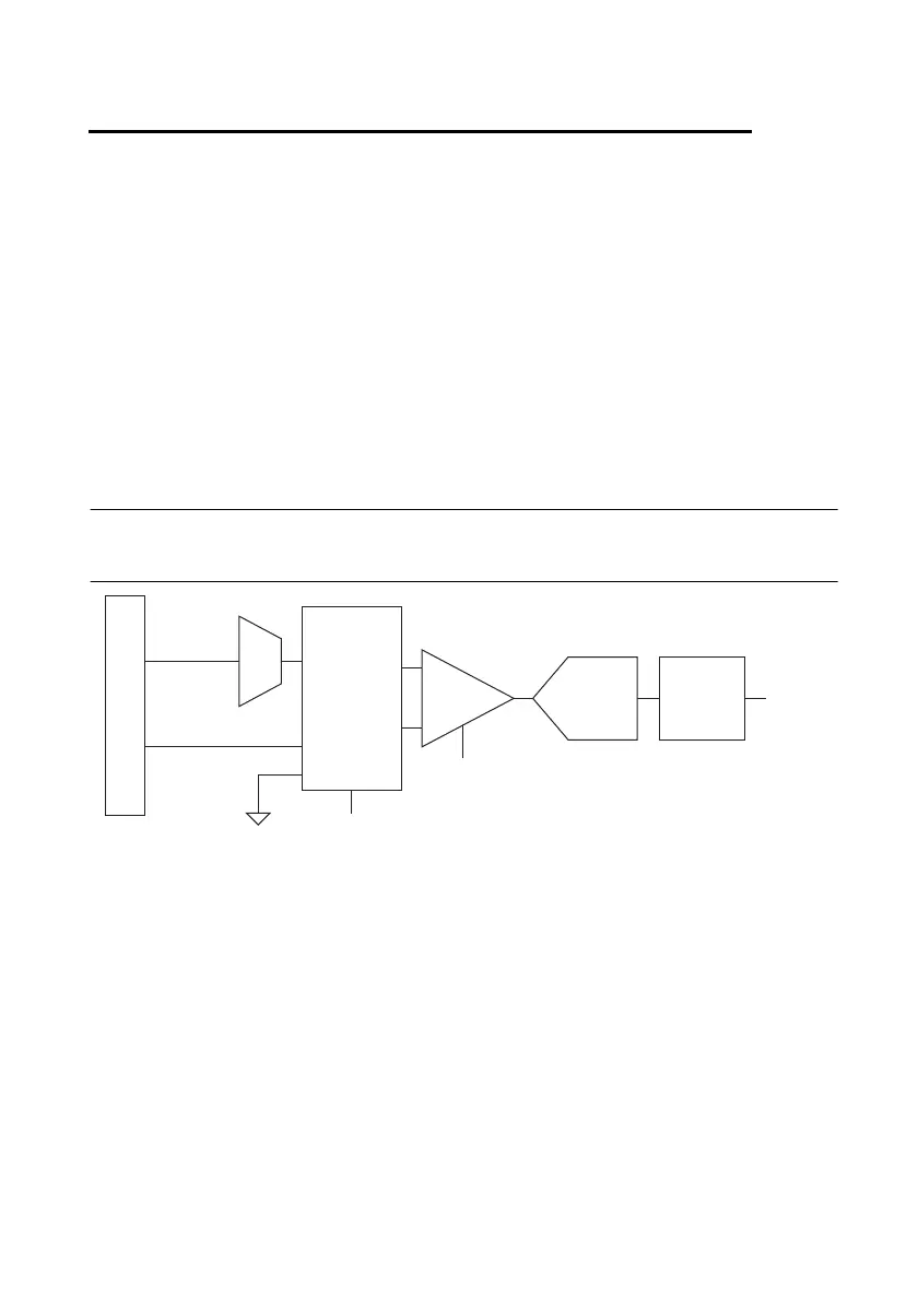
Figure 4-1 shows the analog input circuitry of MIO X Series devices.
Figure 4-1. MIO X Series Analog Input Circuitry
The main blocks featured in the MIO X Series device analog input circuitry are as follows:
• I/O Connector—You can connect analog input signals to the MIO X Series device through
the I/O connector. The proper way to connect analog input signals depends on the analog
input ground-reference settings, described in the Analog Input Ground-Reference Settings
section. Also refer to Appendix A,
Device-Specific Information, for device I/O connector
pinouts.
• Mux—Each MIO X Series device has one analog-to-digital converter (ADC). The
multiplexers (mux) route one AI channel at a time to the ADC through the NI-PGIA.
• Ground-Reference Settings—The analog input ground-reference settings circuitry selects
between differential, referenced single-ended, and non-referenced single-ended input
modes. Each AI channel can use a different mode.
DIFF, RSE,
or NRSE
I/O Connector
AI <0..207>
Mux
AI SENSE
AI GND
NI-PGIA
AI Terminal
Configuration
Selection
Input Range
Selection
ADC
AI FIFO
AI Data

 Loading...