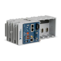
Table 8. RS-232 Serial Port Pinout
Pinout Pin Signal
1 No Connect
2 RI
3 CTS
4 RTS
5 DSR
6 GND
7 DTR
8 TXD
9 RXD
10 DCD
You can use the Ring Indicator (RI) on pin 2 to wake the controller from a low-power state.
You can drive RI with a logic level high to wake the cRIO-904x. Refer to the specifications on
ni.com/manuals for the RI wake voltage.
The following accessories are available to connect the RS-232 serial port to a 9-pin DSUB
plug.
Table 9. RS-232 Serial Port Accessories
Accessory Length Part Number
RS-232, S8 Serial Cable, 10-Position Modular Plug to 9-Pin DSUB 1 m 182845-01
2 m 182845-02
3 m 182845-03
RS-485 Serial Port
The cRIO-904x has an RS-485 serial port that is implemented with an RJ-50, 10-position
modular jack. The RJ-50 connector is isolated from the cRIO-904x. For more information
about the electrical isolation of the RS-485 port, refer to the specifications on ni.com/manuals.
Find examples on how to use NI-Serial or NI-VISA to perform serial communication in the
NI Example Finder. The NI Example Finder is located on the Help menu in the LabVIEW
Help.
The following table shows the pinout for the RS-485 serial port.
cRIO-904x User Manual | © National Instruments | 11

 Loading...