DI Pause Trigger Signal
You can use the DI Pause Trigger signal to pause and resume a measurement acquisition. The
internal sample clock pauses while the external trigger signal is active and resumes when the
signal is inactive. You can program the active level of the pause trigger to be high or low.
Using a Digital Source
To use DI Pause Trigger, specify a source and a polarity. The source can be either from PFI or
one of several other internal signals on your cRIO controller. Refer to the "Device Routing in
MAX" topic in the NI-DAQmx Help or the LabVIEW Help for more information.
Digital Input Filters
When performing a hardware timed task, you can enable a programmable debouncing filter on
the digital input lines of a parallel DIO module. All lines on a module must share the same
filter configuration. When the filter is enabled, the controller samples the inputs with a user-
configured Filter Clock derived from the controller timebase. This is used to determine
whether a pulse is propagated to the rest of the system. However, the filter also introduces
jitter onto the input signal.
In NI-DAQmx, the filter is programmed by setting the minimum pulse width, Tp
2
, that will
pass the filter, and is selectable in 25 ns increments. The appropriate Filter Clock is selected by
the driver. Pulses of length less than 1/2 Tp will be rejected, and the filtering behavior of
lengths between 1/2 Tp and 1 Tp are not defined because they depend on the phase of the
Filter Clock relative to the input signal.
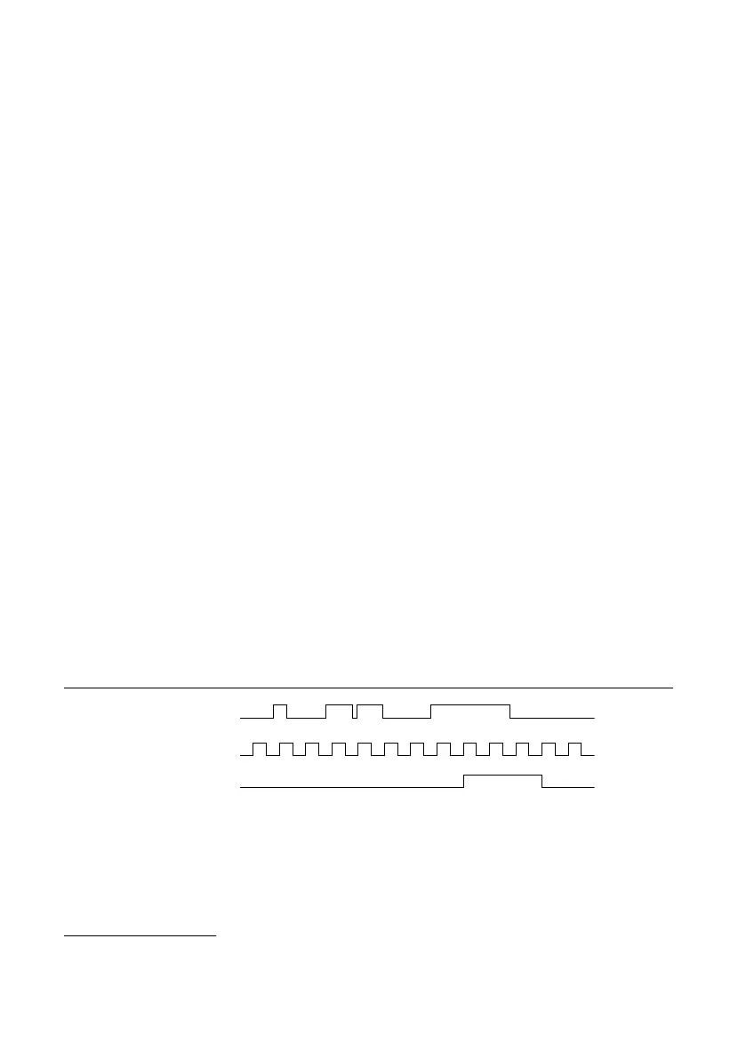
The figure below shows an example of low-to-high transitions of the input signal. High-to-low
transitions work similarly.
Assume that an input terminal has been low for a long time. The input terminal then changes
from low to high, but glitches several times. When the filter clock has sampled the signal high
on consecutive rising edges, the low-to-high transition is propagated to the rest of the circuit.
Figure 41. Filter Example
Digital Input P0.x
Filter Clock
Filtered Input
1 1 21 1 21
Getting Started with DI Applications in Software
You can use the cRIO controller in the following digital input applications:
• Single-point acquisition
• Hardware-Timed Single Point acquisition
2
Tp is a nominal value; the accuracy of the controller timebase and I/O distortion will affect this
value.
cRIO-904x User Manual | © National Instruments | 65

 Loading...