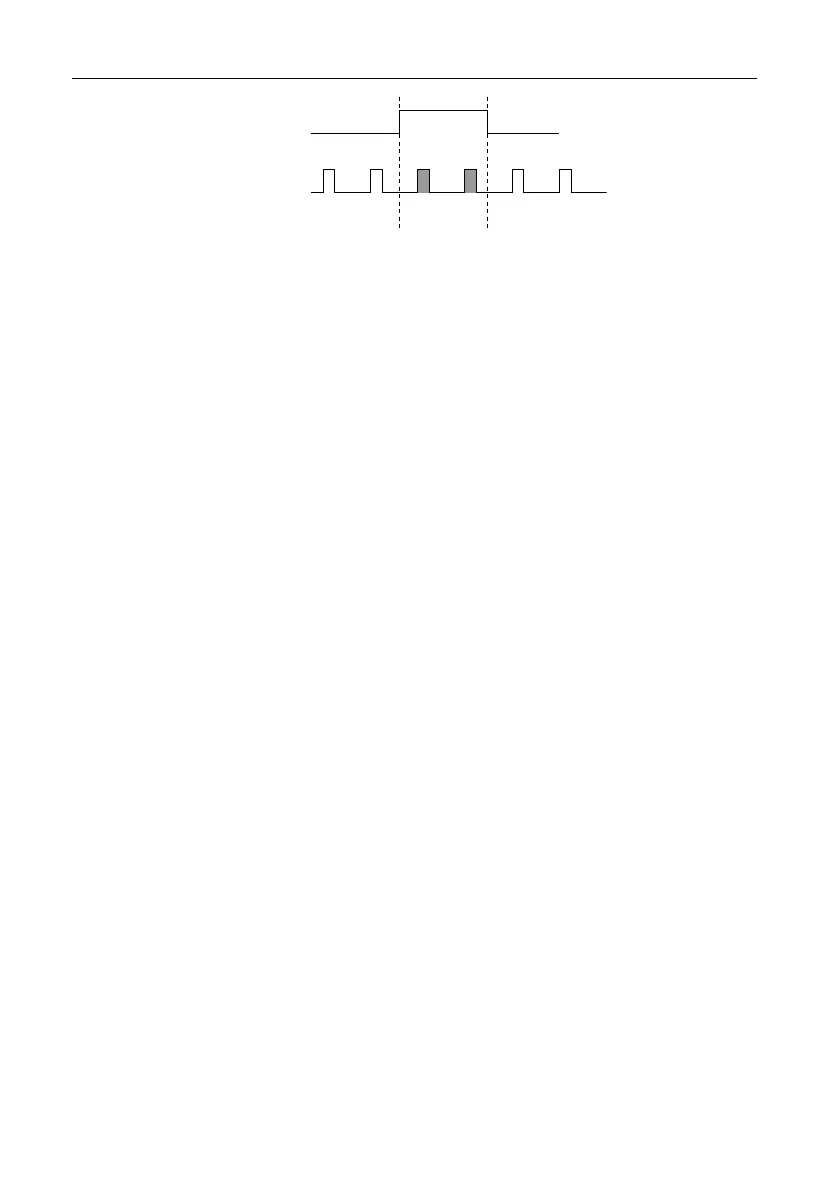
Figure 38. AO Pause Trigger with Other Signal Source
Pause Trigger
Sample Clock
Using a Digital Source
To use AO Pause Trigger, specify a source and a polarity. The source can be a PFI signal or
one of several other internal signals on the cRIO controller.
You also can specify whether the samples are paused when AO Pause Trigger is at a logic high
or low level. Refer to the "Device Routing in MAX" topic in the NI-DAQmx Help or the
LabVIEW Help for more information.
Minimizing Glitches on the Output Signal
When you use a DAC to generate a waveform, you may observe glitches on the output signal.
These glitches are normal; when a DAC switches from one voltage to another, it produces
glitches due to released charges. The largest glitches occur when the most significant bit of the
DAC code changes. You can build a lowpass deglitching filter to remove some of these
glitches, depending on the frequency and nature of the output signal. Go to ni.com/support for
more information about minimizing glitches.
Getting Started with AO Applications in Software
You can use the cRIO controller in the following analog output applications:
• Single-point (on-demand) generation
• Hardware-Timed Single Point generation
• Finite generation
• Continuous generation
• Waveform generation
For more information about programming analog output applications and triggers in software,
refer to NI-DAQmx Help or to the LabVIEW Help.
Digital Input/Output with NI-DAQmx
To use digital I/O, install a digital C Series module into any slot on the cRIO controller. The
I/O specifications, such as number of lines, logic levels, update rate, and line direction, are
determined by the type of C Series module used. For more information, refer to the
documentation included with your C Series module(s).
cRIO-904x User Manual | © National Instruments | 59

 Loading...