Chapter 4 Digital I/O
E Series User Manual 4-8 ni.com
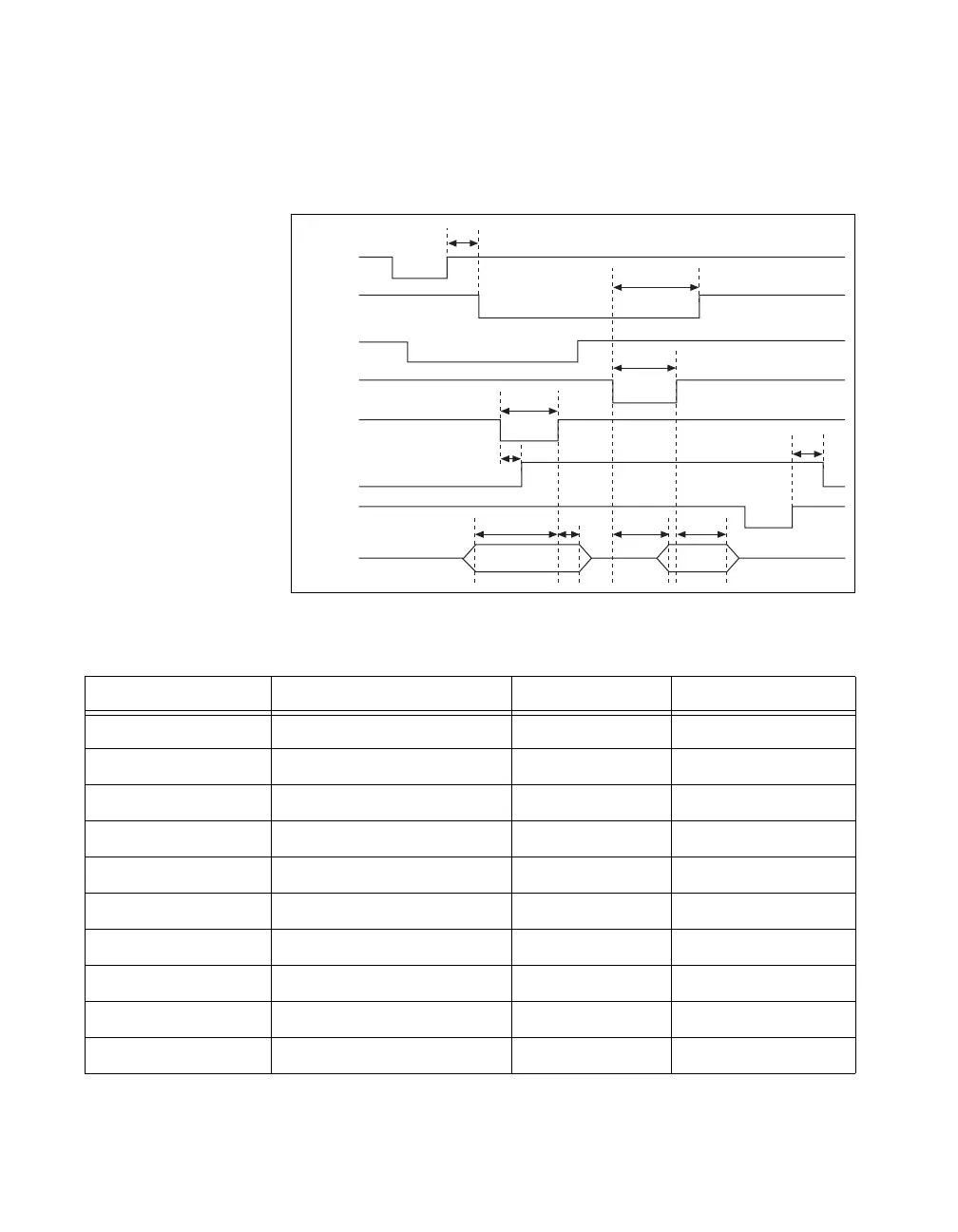
Mode 2 Bidirectional Timing
(NI 6016 and NI 6025E Devices Only) Figure 4-5 and Table 4-5 show timing
specifications for a bidirectional transfer in mode 2.
Figure 4-5. Bidirectional Transfer Timing Specifications
Table 4-5. Bidirectional Transfer Timing Specification
Name Description Minimum (ns) Maximum (ns)
T1 WR* = 1 to OBF* = 0 — 150
T2 Data before STB* = 1 20 —
T3 STB* Pulse Width 100 —
T4 STB* = 0 to IBF = 1 — 150
T5 Data after STB* = 1 50 —
T6 ACK* = 0 to OBF* = 1 — 150
T7 ACK* Pulse Width 100 —
T8 ACK* = 0 to Output — 150
T9 ACK* = 1 to Output Float 20 250
T10 RD* = 1 to IBF = 0 — 150
T1
T6
T7
T3
T4
T10
T2 T5 T8 T9
WR *
OBF *
INTR
ACK *
STB *
IBF
RD *
DATA

 Loading...


