Chapter 8 Real-Time System Integration Bus (RTSI)
E Series User Manual 8-2 ni.com
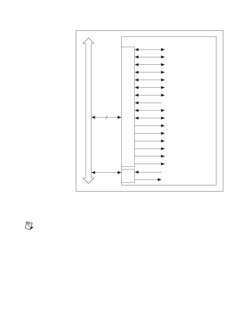
Figure 8-1. PCI E Series Signal Connection Scheme
Refer to the
Timing Signal Routing section of Chapter 7, Digital Routing,
for a description of the signals shown in Figure 8-1.
Note In NI-DAQmx, you can indirectly route timing signals not shown in the above
diagrams to RTSI. For a detailed description of which routes are possible on your device,
in MAX, select Devices and Interfaces, your device, then select the Device Routes tab.
PXI E Series Devices
The RTSI trigger lines connect to other devices through the PXI bus on the
PXI backplane. RTSI <0..5> connect to PXI Trigger <0..5>, respectively.
This signal connection scheme is shown in Figure 8-2. The RTSI Clock is
connected to PXI Trigger 7. In PXI, RTSI 6 connects to the PXI star trigger
line, allowing the device to receive triggers from any star trigger controller
RTSI Bus Connector
RTSI Trigger 7
DAQ-STC
ai/StartTrigger
ai/ReferenceTrigger
ao/SampleClock
ao/StartTrigger
Ctr0Source
Ctr0Gate
Ctr0InternalOutput
Ctr0Out
ai/SampleClock
ai/PauseTrigger
ai/SampleClockTimebase
ao/SampleClockTimebase
Ctr1Source
Ctr1Gate
20MHz Timebase
Master Timebase
RTSI Switch
Switch
Trigger <0..6>
ai/ConvertClock
ao/PauseTrigger

 Loading...


