© National Instruments Corporation 2-1 E Series User Manual
2
Analog Input
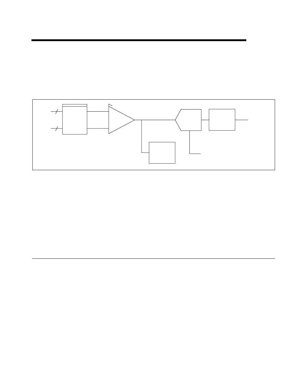
Figure 2-1 shows the analog input circuitry of E Series devices.
Figure 2-1. Analog Input Circuitry Block Diagram
E Series AI signals include the following signals: AI <0..15>, AI SENSE,
and AI GND. The NI 6031E/6033E/6071E devices include AI <16..63>
and AI SENSE 2 in addition to the previous list of signals. The type of input
signal source and the configuration of the AI channels being used
determine how you connect these AI signals to the E Series devices. This
chapter provides an overview of the different types of signal sources and AI
configuration modes.
Analog Input Circuitry
Mux
Each E Series device has one analog-to-digital converter (ADC). The
multiplexer (mux) routes one AI channel at a time to the ADC through the
NI-PGIA. The mux also gives you the ability to use three different analog
input terminal configuration. For more information, refer to the
Analog
Input Terminal Configuration section.
Analog
Trigger
Mux
AI+
AI–
AI FIFO
ADC
AI Data
AI Timing Signals
NI-PGIA
Analog
Trigger
Mux
AI+
AI–
AI FIFO
ADC
AI Data
AI Timing Signals
NI-PGIA

 Loading...


