Chapter 5 Counters
© National Instruments Corporation 5-5 E Series User Manual
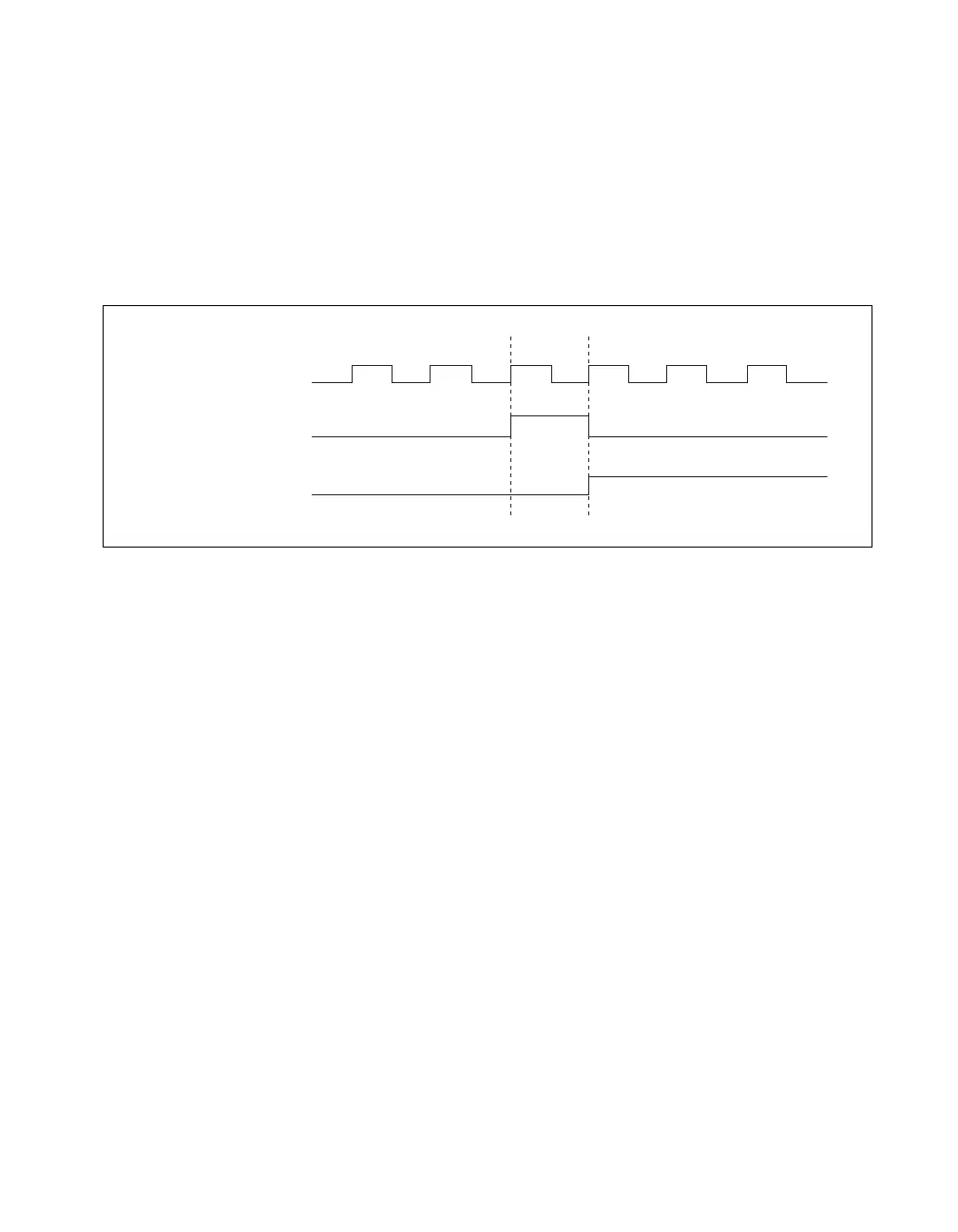
Counter 0 Internal Output Signal
The Counter 0 Internal Output (Ctr0InternalOutput) signal is the output of
Counter 0. This signal reflects the terminal count (TC) of Counter 0. The
counter generates a terminal count when its count value rolls over. The
two software-selectable output options are pulse on TC and toggle output
polarity on TC. The output polarity is software-selectable for both options.
Figure 5-5 shows the behavior of the Ctr0InternalOutput signal.
Figure 5-5. Ctr0InternalOutput Signal Behavior
You can use Ctr0InternalOutput in the following applications:
• In pulse generation mode, the counter drives Ctr0InternalOutput with
the generated pulses. To enable this behavior, software configures the
counter to toggle Ctr0InternalOutput on TC.
• Ctr0InternalOutput can control the timing of analog input acquisitions
by driving the following signals:
– ai/SampleClock
– ai/StartTrigger
– ai/ConvertClock
• Counter 0 and 1 can be daisy-chained together by routing
Ctr0InternalOutput to Ctr1Gate.
• Ctr0InternalOutput can drive any of the RTSI <0..6> signals to control
the behavior of other devices in the system.
• Ctr0InternalOutput drives the CTR 0 OUT pin to trigger or control
external devices.
• Ctr0InternalOutput can drive other internal signals.
Refer to Device Routing in MAX in the NI-DAQmx Help or the
LabVIEW 8.x Help for more information.
Ctr0Source
Ctr0InternalOutput
(Pulse on TC)
Ctr0InternalOutput
(Toggle Output on TC)
TC

 Loading...


