Chapter 5 Counters
© National Instruments Corporation 5-7 E Series User Manual
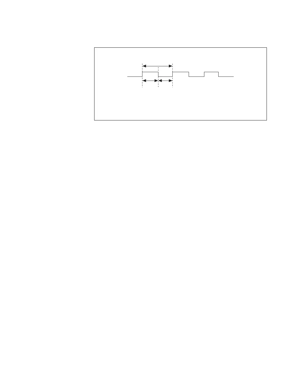
Figure 5-7 shows the timing requirements for the Ctr1Source signal.
Figure 5-7. Ctr1Source Signal Timing Requirements
The maximum allowed frequency is 20 MHz, with a minimum pulse width
of 10 ns high or low. There is no minimum frequency.
For most applications, unless you select an external source, the
20MHzTimebase signal or the 100kHzTimebase signal generates the
Ctr1Source signal.
Counter 1 Gate Signal
You can select any PFI as well as many other internal signals like the
Counter 1 Gate (Ctr1Gate) signal. The Ctr1Gate signal is configured in
edge-detection or level-detection mode depending on the application
performed by the counter. The gate signal can perform many different
operations including starting and stopping the counter, generating
interrupts, and saving the counter contents.
You can export the gate signal connected to Counter 1 to the PFI 4/CTR 1
GATE pin, even if another PFI is inputting the Ctr1Gate signal. This output
is set to high-impedance at startup.
t
p
= 50 ns minimum
t
w
= 10 ns minimum
t
w
t
w
t
p

 Loading...


