Chapter 4 Digital I/O
© National Instruments Corporation 4-3 E Series User Manual
82C55A configurations as modes, whereas NI-DAQ, LabWindows/CVI, and LabVIEW
documentation refers to them as handshaking and no handshaking.
Power-On State
(NI 6016 and NI 6025E Devices Only) The NI 6016 and NI 6025E contain bias
resistors that control the state of the DIO lines, P1.<0..7>, P2.<0..7>,
P3.<0..7>. At power-on, each DIO line is configured as an input and pulled
high.
You can change the power-on state of individual lines from pulled high to
pulled low by adding your own external resistors.
Changing DIO Power-On State to Pulled Low
Each DIO line is pulled to V
cc
(approximately +5 VDC) with a 100 kΩ
resistor. To pull a specific line low, add a pull-down resistor (R
L
) between
the line and ground so the maximum value on the line is 0.4 VDC. The DIO
lines provide a maximum of 2.5 mA at 3.7 V in the high state. Using the
largest possible resistor ensures that you do not use more current than
necessary to perform the pull-down task.
Ensure the value of the resistor is not so large that leakage current from the
DIO line, along with the current from the 100 kΩ pull-up resistor, drives the
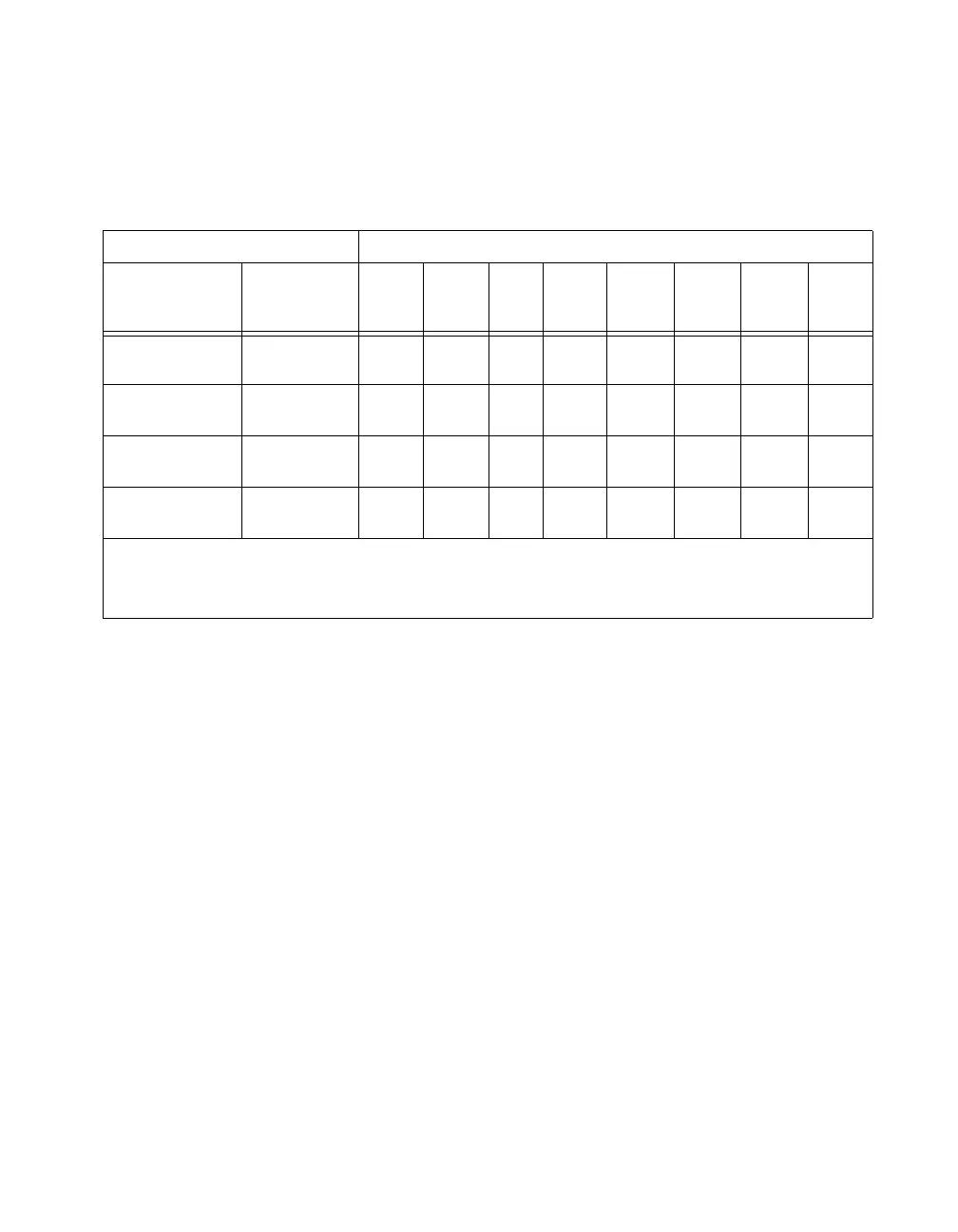
Table 4-1. Configuration Terminology and Signal Assignments
Configuration Terminology Signal Assignments
NI 6016 or
NI 6025E
National
Instruments
Software
P3.7 P3.6 P3.5 P3.4 P3.3 P3.2 P3.1 P3.0
Mode 0
(Basic I/O)
No
Handshaking
I/O I/O I/O I/O I/O I/O I/O I/O
Mode 1
(Strobed Input)
Handshaking I/O I/O IBF
1
STB
*1
INTR
1
STB
*2
IBFB
2
INTR
2
Mode 1
(Strobed Output)
Handshaking OBF
*1
ACK
*1
I/O I/O INTR
1
ACK
*2
OBF
*2
INTR
2
Mode 2
(Bidirectional Bus)
Handshaking OBF
*1
ACK
*1
IBF
1
STB
*1
INTR
1
I/O I/O I/O
*
Indicates that the signal is active low.
1
Denotes port 1 handshaking signals.
2
Denotes port 2 handshaking signals.

 Loading...


