Chapter 8 Real-Time System Integration Bus (RTSI)
© National Instruments Corporation 8-3 E Series User Manual
plugged into Slot 2 of the chassis. E Series devices can accept timing
signals from the PXI star trigger line, but they cannot drive signals onto it.
For more information about the star trigger, refer to the PXI Hardware
Specification Revision 2.1.
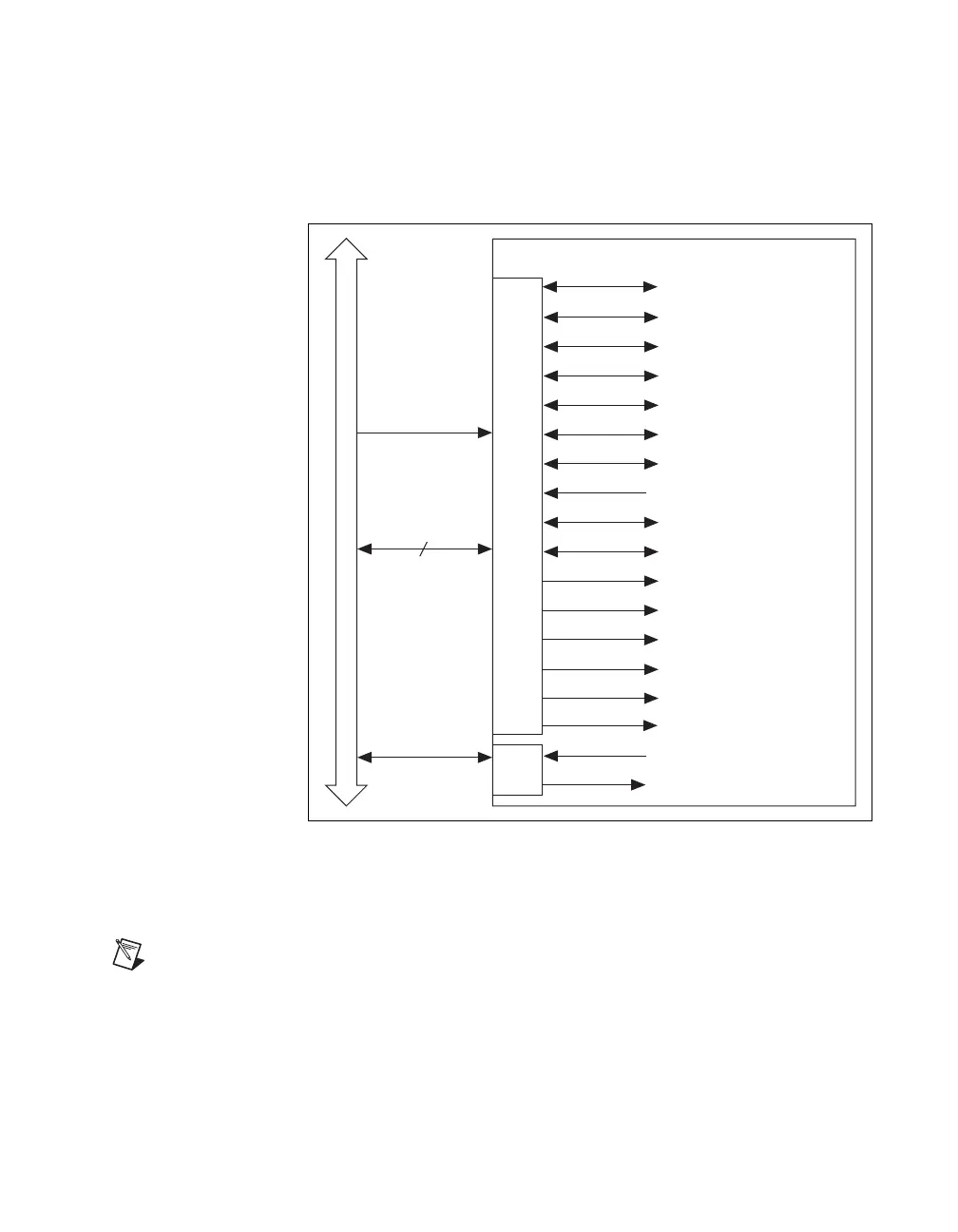
Figure 8-2. PXI E Series Signal Connection Scheme
Refer to the
Timing Signal Routing section of Chapter 7, Digital Routing,
for a description of the signals shown in Figure 8-2.
Note In NI-DAQmx, you can indirectly route timing signals not shown in the above
diagrams to RTSI. For a detailed description of which routes are possible on your device,
in MAX, select Devices and Interfaces, your device, then select the Device Routes tab.
6
PXI Bus Connector
PXI Trigger 7
DAQ-STC
ai/StartTrigger
ai/ReferenceTrigger
ao/SampleClock
ao/StartTrigger
Ctr0Source
Ctr0Gate
Ctr0InternalOutput
Ctr0Out
ai/SampleClock
ai/PauseTrigger
ai/SampleClockTimebase
ao/SampleClockTimebase
Ctr1Source
Ctr1Gate
20MHz Timebase
Master Timebase
RTSI Switch
Switch
PXI Trigger <0..5>
PXI Star 6
ai/ConvertClock
ao/PauseTrigger

 Loading...


