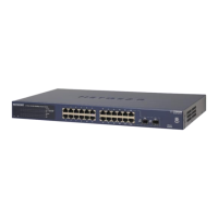
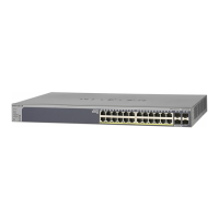
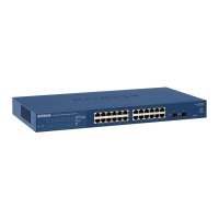
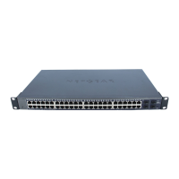
Table 1. Front panel components (Continued)
DescriptionNumber
2 dedicated SFP fiber ports in which you can install GBICs for fiber connections.
For more information, see SFP ports for fiber connectivity on page 16.
5
Factory Defaults button (model GS724TPv2 only).
For more information, see Dual-function Factory Defaults button (model GS724TPv2) on page 17.
6
LEDs
This section describes the LEDs on the front panel of the switch.
Table 2. Front panel LEDs
DescriptionLED
Solid green. The switch is powered on.
Solid amber. The switch is booting.
Off. Power is not supplied to the switch.
Power LED
Solid amber. The internal fan failed.
Off. The internal fan is operating normally.
Fan LED
Off. Sufficient (more than 7W of) PoE power is available.
Solid amber. Less than 7W of PoE power is available.
Blinking amber. At least once during the previous two minutes, less than 7W
of PoE power was available.
PoE Max LED
Off. No Ethernet link is established.
Solid green. A 1000 Mbps Ethernet link is established.
Blinking green. The port is transmitting or receiving packets at 1000 Mbps.
Solid amber. A 10 Mbps or 100 Mbps Ethernet link is established.
Blinking amber. The port is transmitting or receiving packets at 10 Mbps or
100 Mbps.
RJ-45 upper LEDs 1–24
These LEDs indicate the link
status, speed, and activity
of an associated port.
Off. The port is not delivering PoE.
Solid green. The port is delivering PoE.
Solid amber. A PoE fault occurred. For more information, see PoE
troubleshooting suggestions on page 34.
RJ-45 lower LEDs 1–24
These LEDs indicate the
PoE status of an associated
port.
Off. No SFP module link is established.
Solid green. A 1000 Mbps link is established.
Blinking green. The SFP fiber port is transmitting or receiving packets at 1000
Mbps.
Link and ACT LEDs 25F–26F
Hardware Installation Guide14Hardware Overview
24-Port Gigabit (Hi-Power) PoE+ Ethernet Smart Managed Pro Switch with 2 SFP Ports
 Loading...
